background image


© Tinius Olsen Ltd 

L-Series Manual – Issue 1 

Page 24 of 31 


6.5.2.  Load Limit Alarm 

A load limit alarm is flagged when the machine or load cell capacity is exceeded either 

in tension or compression.  The value of the alarm depends upon the load cell fitted and 

is approximately 9% greater than load cell capacity.  E.g. If a 10KN load cell was fitted 

to a H50KL machine the alarm would be triggered at 10.9kN in tension or compression.  

This system should not be relied on to protect the machine or operator, as the 

machine’s ability to stop prior to damage is greatly reduced at high crosshead speeds. 


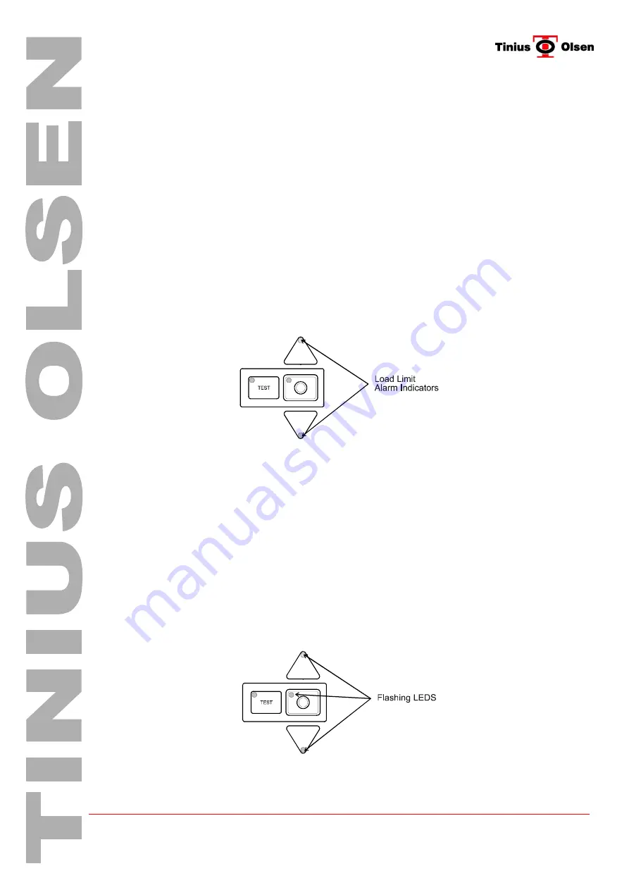
The alarm direction is indicated by the Flashing LED indicator on the appropriate 

direction key, reporting an alarm message on the software control panel and audible 

alarm.  The alarm can be cleared by backing the crosshead off in the opposite direction 

to reduce the applied force using the appropriate direction key.  If the alarm persists it is 

possible that the load cell has been damaged. 


Note  A load limit alarm can be triggered if the load cell is not fitted or incorrectly 

installed.  The direction key which is indicating the alarm will be disabled. This is to 

protect the machine or load cell in the event of incorrect direction selection. 


The diagram below indicates the Load Limit alarm indicators. 


6.5.3.  Emergency Stop Alarm 

Activation of the emergency stop switch is by pressing the top of the switch downwards.  

On activating the emergency stop switch the machine will be placed into a stop 

condition and flag an emergency stop alarm by flashing both direction and stop LED 

indicators, reporting an alarm message on the software control panel and audible alarm. 


To reset the emergency stop switch rotate the top part of the switch clockwise (direction 

shown by arrows on top of switch).  On rotation the top will spring upwards returning the 

switch to its normal position.  To clear the alarm indicators select ‘OK’ on the software 

alarm panel.  This panel automatically appears when an alarm condition is present.  The 

machine will now return to normal operation. 


Note  Resetting the emergency stop alarm by powering the machine OFF and ON 

again may require restarting the software. 


Summary of Contents for H10KL

Page 1: ...rrywood Business Park Honeycrock Lane Salfords Surrey RH1 5DZ England UK Telephone 44 1737 765001 Facsimile 44 1737 764768 Website www tiniusolsen com L Series Tensile Test Machines Instructions For Use Issue 01 ...

Page 2: ...4 Contents 13 4 1 Checking Contents 13 5 Machine Installation 15 5 1 Location 15 5 2 Mains Supply 15 5 3 Warning Symbols 16 5 4 Connection to Supply 16 5 5 Fitting Load Cell 17 5 6 Connection to PC 18 6 Power ON Checks 20 6 1 Emergency Stop Switch 20 6 2 Power ON OFF Switch 20 6 3 Mechanical Limit Switches 21 6 4 Crosshead Control Keys 22 6 5 Alarms 23 6 6 Auxiliary Equipment 25 7 Installation of ...

Page 3: ...L 25KN and H50KL 50KN All machines are similar in functionality and are supplied with the same auxiliary interface The L Series range of testing machines employs two load frame configurations A single screw arrangement for low capacity machines H1KL and H5KL and a twin screw arrangement for high capacity machines H10KL H25KL and H50KL All L Series machines are supplied with an external Power Trans...

Page 4: ...m Maximum Test Specimen Diameter 200mm Frame Stiffness 7kN mm at normal load points H10KL Maximum crosshead travel excluding grips is 1100mm Distance between Columns 405mm Frame Stiffness 100kN mm at normal load points H25KL Maximum crosshead travel excluding grips is 1100mm Distance between Columns 405mm Frame Stiffness 100kN mm at normal load points H50KL Maximum crosshead travel excluding grips...

Page 5: ... to 1kN Return Speed 0 001 mm min to 1500 mm min Jog Speed 0 001 mm min to 1000 mm min H5KL 0 001 mm min to 500 mm min up to 2 5kN 0 001 mm min to 1000 mm min up to 5kN Return Speed 0 001 mm min to 1500 mm min Jog Speed 0 001 mm min to 1000 mm min H10KL 0 001 mm min to 500 mm min up to 5kN 0 001 mm min to 1000 mm min up to 10kN Return Speed 0 001 mm min to 1000 mm min Jog Speed 0 001 mm min to 100...

Page 6: ...nally Fused 5x20mm HRC 6 30A Type T for 230V Supply 2 11 Machine Supply Requirements H1KL 48v 10 50 60Hz 330VA H5KL 48v 10 50 60Hz 330VA H10KL 48v 10 50 60Hz 530VA H25KL 48v 10 50 60Hz 530VA H50KL 48v 10 50 60Hz 530VA 2 12 CE Mark EMC Directive 89 336 EEC and conforms to the following Generic EMC specification for Commercial and Light Industrial products Emissions EN 50081 1 Immunity EN 50082 1 Lo...

Page 7: ...ate The machine is delivered packed in a Tri wall cardboard case This case has pallet style blocks at its base enabling the case to be moved with a fork lift truck The diagram below shows the machine as delivered 3 1 1 Cut all straps Care must be taken as these straps are under tension 3 1 2 Cut tape at top of case to enable the access and remove internal top packing The diagram below indicates pa...

Page 8: ...se cartons as they may be heavier than first expected The diagram below indicates the location of internal cartons 3 1 5 Remove base packing from the machine by lifting the machine vertically Whilst carying out this operation it is an ideal opportunity to transfer the machine to the prepared location Caution This material testing machine weighs 50Kg 110 pounds It is recommended two or more people ...

Page 9: ... Tinius Olsen Ltd L Series Manual Issue 1 Page 9 of 31 3 1 6 Remove the protective packing around the electronic control panel ...

Page 10: ... be shipped on its back This is to enable easier transportation for air shipment etc The diagram below shows the machine as delivered 3 2 1 Place Upright Before attempting to unpack the machine the case must be stood on end bottom end indicated by pallet style blocks Rotating the case to its upright position should not be attempted by hand and will require a overhead hoist or fork lift truck The d...

Page 11: ...s the position of additional cartons 3 2 3 Remove Constraints The machine is held in position by packing material at top and bottom and by a shipping restraint beam mounted at the machines crosshead Remove the shipping restraint beam This beam is held in position by screws each side of the case Finally remove all packing material The diagram below indicates the shipping restraint bead to be remove...

Page 12: ... the forks do not hit the machine side covers Raise the forks to lift the machine so that its base is clear of the case then remove the machine form the case Note To stop damage to the paint work on the machines crosshead place strips of cardboard on the forks before lifting The diagram below indicates machine lifting positions If a fork lift truck is not available the machine may removed using a ...

Page 13: ...unting stud s with different threads depending on the capacity of the load cell s supplied 4 1 2 Nose Piece 25 kN capacity 5 8 diameter nose piece attachments and 5 16 diameter Grip Pins machines above 25 kN will also be provided with a set of 50 kN capacity with 3 4 diameter nose piece attachments and 3 8 diameter Grip Pins 4 1 3 Breaker Bar 1 4 diameter Breaker Bar 5 16 bar with 10 kN and larger...

Page 14: ... each item Load Cell Nose Piece Attachment Grip Pins Load Cell Bolt Sleeve Breaker Bar Hex Key Bolt Washer Hex Key Mounting Studs Power Transformer RS232 Lead Operating Manual Calibration Certificate Additional parts may be supplied which are not listed above and will depend on the system configuration ...

Page 15: ...n in the above diagram The transformer voltage is indicated on the power transformer label and will require a supply connector to be fitted The supply cable must be connected as follows Brown Live Blue Neutral Yellow Green Earth NOTE External Power Transformer MUST BE EARTHED Under no circumstance must the machine be operated without an earth connection Positioning of the machine and external powe...

Page 16: ... the test 5 3 2 Power Transformer Hazardous Warning Symbol The power transformer hazardous warning symbol is located on the front of the unit next to the serial number voltage power label It indicates that the unit is operating at a HAZARDOUS VOLTAGE and the operator must refer to the operating instructions regarding Installation Environment Operating Voltage Connection and Maintenance Power and V...

Page 17: ...nly Use the hex key provided to tighten the cell in place Before mounting any load cells to the crosshead always check to insure that the contact surfaces are clean Connect the load cell by plugging the 15 pin connector into the load cell socket just under the crosshead Care must be taken when mounting the cell as it is handed The correct orientation is with the slot to the top and cable at the re...

Page 18: ... twin screw machines is with the slot to the left and cable to the right The diagram below indicates how to mount the load cell to a twin screw machine H10KL H25KL H50KL Align the load cell with the with mounting hole beneath the crosshead Place the mounting stud through crosshead and screw into load cell Hold load cell in safe area and position it parallel to the crosshead then fully tighten with...

Page 19: ...le socket connectors to its mating plug on the machine taking care not to bend any pins whilst held in this position tighten the two socket jack screws until the connector is fully engaged The diagram below indicates position of machine RS 232 Port The other end of the RS 232 serial cable connects to the PC Computer RS 232 Port Com 1 located at the rear of the PC Base Unit The method is the same a...

Page 20: ...utton H1KL H5KL Emergency and Power Switch located on right hand side of machine H10KL H25KL H50KL Emergency and Power Switch located on left hand side of machine 6 1 2 Operation To check if the emergency stop switch is in its normal position rotate the top part of the switch clockwise direction shown by arrows on top of switch If the switch had been previously activated on rotation the top will s...

Page 21: ... both single and twin screw machines There are slight differences in the arrangement of the limit switches the single screw machines having them located in the side cover and the twin screw machines being located on a slider rod The diagram below shows the location of the mechanical crosshead limit switches Adjustment of the limit switches are similar for both types of machine The limit switches a...

Page 22: ...ere are two crosshead directional arrows a STOP key and a TEST Mode key The UP direction arrow key is used for raising the crosshead the STOP key for stopping the crosshead and the DOWN direction arrow key for lowering the crosshead Each of these keys have a LED to indicate the mode selected Pressing one of the directional arrow keys once will run the crosshead at the first default speed Power ON ...

Page 23: ...the machine to the power ON defaults speeds settings 6 5 Alarms 6 5 1 Alarm Indicators Crosshead Limit Alarm A crosshead limit alarm is flagged when the crosshead strikes either crosshead limit switch and places the machine into a stop condition The indication that an alarm is present is by a Flashing LED indicator on either direction key reporting an alarm message on the software control panel an...

Page 24: ...ote A load limit alarm can be triggered if the load cell is not fitted or incorrectly installed The direction key which is indicating the alarm will be disabled This is to protect the machine or load cell in the event of incorrect direction selection The diagram below indicates the Load Limit alarm indicators 6 5 3 Emergency Stop Alarm Activation of the emergency stop switch is by pressing the top...

Page 25: ...perature and power back ON If the fault continues turn OFF machine isolate from supply and call TINIUS OLSEN service department Note Resetting the motor drive alarm by powering the machine OFF and ON again may require restarting the software 6 6 Auxiliary Equipment Auxiliary Port The auxiliary port is located at the front right hand side of the machine s base This port allows connection to a range...

Page 26: ...ll first ensure both locking collars are centralised on the tooling attachment Align the fixing thread to the load cell and rotate in a clockwise direction to engage Once engaged rotate a further 6 to 8 times This is to ensure the correct amount of thread has been inserted Ensure the tooling attachment hole is facing forward Now rotate the fixing locking collar clockwise until it makes contact wit...

Page 27: ... Issue 1 Page 27 of 31 The diagram below indicates the HW20 Wedge Grip fitted to the load cell Note The HW20 Wedge Grip is shown as an example the same principals apply to all tooling using this type of attachment 7 3 Tooling Alignment ...

Page 28: ...nd retighten collars Repeat this procedure until the tooling is aligned Fully tighten the fixed crosshead locking collars with the breaker bar supplied Care must be taken when tightening locking collars attached to a load cell as lower capacity load cells can be damaged from excess torque To minimise risk of damage ensure the sensitive area of the load cell is supported when tightening these locki...

Page 29: ...ly however interlocked screens machine cannot be operated with screen open must be factory fitted The operator must assess the type of sample failure prior to testing This assessment will enable the correct protective screen to be selected Generally with ductile materials with low failure energy no screen is required As failure energy increases the risk of injury to the operator increases The type...

Page 30: ... mounted in a clip type fuse holder Simply unclip the blown fuse and replace with a new fuse Refit the transformer cover and retaining screws including locking washers Reconnect the external power transformer to the machine and mains supply Power the machine On and check its function If the machine does not power up it has a fault and has possibly blown the protection fuse again Do not attempt to ...

Page 31: ... damage to the wedges inserts or even the grip housings This 50 50 Mixture is available from TINIUS OLSEN 9 4 Machine Storage Long Term Storage If the machine is not to be used for some time ensure that it is unloaded and the supply to the external power transformer is disconnected To help to keep the machine clean cover the machine with a protective cover If the machine is to be stored outside it...

Reviews: