background image

Timpdon Electronics


Tel    0161 - 980 7804 

Issue 2 – October 2010 


Web


www.timpdon.co.uk 


EMail  [email protected]  


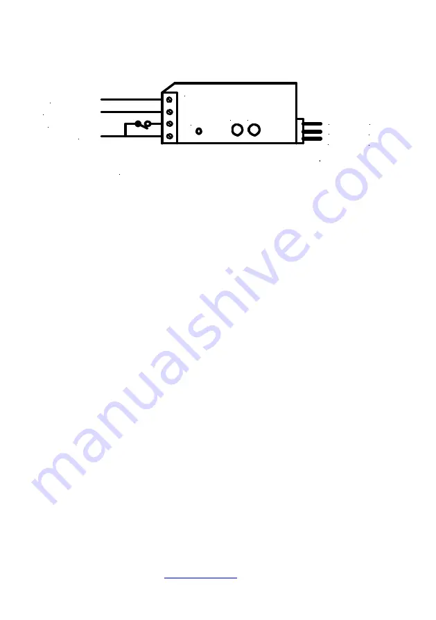
Installation and Wiring 


Operating
Switch
[Closed = Set]

S1 S2

LED

V+

Control

0V

Red

Yellow

Black

Connections to Servo

+4.8 to +6V

0 V

SCS2

Sense Output

Switch Input


Notes 


Connect a d.c. supply of between 4.8 V and 6V to the screw terminals, as 

shown. – Please read the 

Cautionary Notes

 below, before selecting your 

power source. 


Do not exceed the maximum permitted nominal supply voltage of 6 V. 
Although the 

SCS2

 will accommodate higher voltages without blowing up, 

many RC servos will not. 


Ensure that the power supply polarity is correct before powering up. 


Connect a single pole operating switch between the switch input terminal 

and the 0V supply, as shown. Note that the 

Reset

 position of the servo, as 

described below, corresponds to the 

switch open

 condition, and the 

Set


position to 

switch closed


The sense output will switch from +5V to 0V on completion of a 

Set


operation, and will switch back from 0V to +5V on completion of a 

Reset


operation. 


This output may be connected to the switch input of another 

SCS2

 [or 

SCS1

] to permit sequential operation, with the motion of the second servo 

starting on completion of movement of the first, and/or used to power an 
external indicator to display the current state [

Set

 or 

Reset

] of the servo. 


Note that the maximum permitted load current on this output is 20mA. 


Plug the servo connector on to the three pin plug connector on the 
opposite end of the 

SCS2

. Ensure that the 

black

 wire on the servo is 

positioned towards the bottom edge of the 

SCS2

, adjacent to the 0V screw 

terminal. 

Summary of Contents for SCS2

Page 1: ...nce Programmed settings retained when power removed Sense output at end of throw in both directions permits daisy chaining of units with sequential operation or external indication of servo position Ideal for control of crossing gates points and semaphore signals Digital microprocessor controlled Small size 50mm x 25mm x 16mm 4 8 V to 6 V d c supply Screw terminals for connections to supply contro...

Page 2: ...witch input terminal and the 0V supply as shown Note that the Reset position of the servo as described below corresponds to the switch open condition and the Set position to switch closed 3 The sense output will switch from 5V to 0V on completion of a Set operation and will switch back from 0V to 5V on completion of a Reset operation This output may be connected to the switch input of another SCS2...

Page 3: ...ther direction of travel program the relevant bounce level to zero bounce 3 Once the servo has reached its programmed end position and after a further 1 second delay the sense output will switch to the opposite state For Set the output will switch from 5V to 0V and for Reset from 0V to 5V If this output is connected to the switch input of another servo controlled switch the second unit will start ...

Page 4: ...bered by the SCS2 and need not be set again Programming Programming or re programming may be performed at any time using push button switches S1 and S2 with indication provided by the LED indicator Programming is performed in five steps in order Set Position Reset Position Rotation Speed Reset Bounce Level and Set Bounce Level No new programmed settings will be saved unless all five programming st...

Page 5: ...e servo will rotate continuously between the two end positions which have already been programmed at the current rotation speed There are sixteen steps of rotation speed varying from about 0 25 s to 20 s for 90 degree rotation Press and release S2 to increase the speed by one step or press and release S1 to decrease it by one step Please read the Cautionary Notes below before attempting to use ver...

Page 6: ...ogramming step 5 the servo will rotate continuously between the programmed Set position and the position represented by current Set Bounce level at the programmed rotation speed There are sixteen steps of bounce level varying from zero to approximately 20 of the programmed servo range between Set and Reset Press and release S2 to increase the bounce level by one step or press and release S1 to dec...

Page 7: ...arrangements before assuming that the SCS2 is faulty and returning it for repair 2 Although the rotation rate of the SCS2 can be programmed to a maximum speed of 0 25 seconds for 90 degree rotation many servos can not achieve this speed If you program a rotation speed higher than the servo can actually achieve the servo will not be able to keep up with the programmed output of the SCS2 when moving...

Page 8: ...o uk Other Timpdon ServoSwitches Model SCS1 User Notes Identical in performance and operation to SCS2 but without the sense output Recommended for use for control of single signals or points or at the end of a series of daisy chained SCS2 units where no further sequential operation of servos is required ...

Reviews: