User Manual-TA16
Version
D
January 2021
19 of 22
19
3.
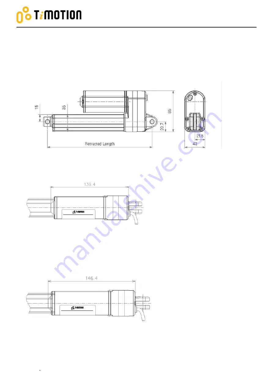
Product specifications
2D drawings
3.1
A. Dimensions
–
Standard for Load and Speed Code A, B, C, D (mm)
B. Dimensions
Standard for Load and Speed Code K, J, G (mm)
Page 1: ...User Manual TA16 Version E January 2021 1 of 22 A User Manual TA16...
Page 2: ...rtant notice 8 2 2 2 Cable 9 2 2 3 Inrush current 10 Wiring definitions 11 2 3 2 3 1 Limitations for limit switches output signals 11 2 3 2 Two limit switches to cut the current without signal output...
Page 3: ...f stroke Low LS Lower limit switch is installed in fully retracted end of stroke Mid LS Middle limit switch is installed and the position is set by customer s request N C It is the pin of limit switch...
Page 4: ...arget Personnel 1 2 Please allow qualified mechanical and electrical professionals to perform all installation maintenance and replacement of the TiMOTION products Please keep the products away from p...
Page 5: ...1 Mounting dismounting the actuator Please read through this user manual before working on the equipment that the actuator is or shall be a part of Adhere to the information contained in this user ma...
Page 6: ...secured safely and can withstand the wear Stop the actuator immediately if anything unusual is observed Ensure there is no side load present on the actuator Only use the actuator within the specified...
Page 7: ...t threaded at both ends of the attachments Do not mount the actuator with the pins in different rotated angles this could cause stress on the nut during operation The load should act along the stroke...
Page 8: ...please ensure it is able to withstand the peak of high voltage To reduce the chance of interference refrain from placing signal cables along power cables Use a two wire system to prevent ground loop P...
Page 9: ...tuator is supplied with a power cable and or signal cable The standard cable s for industrial applications has have flying leads in the end for the user s equipment connections Please refer to the app...
Page 10: ...uator starts to work there is an inrush current to the motor that will be less than 0 2 seconds up to four times the rated current Please select a power supply that is able to withstand the inrush cur...
Page 11: ...he function limitations for limit switches to output signals are shown in the table below Functions for limit switches Signal output Without POT Single Hall Double Hall 2 limit switches to cut the cur...
Page 12: ...rent of the motor when the actuator moves to the end of each stroke and without any output signal Wire AWG Description Spec Green 20 Connect to Vm to extend the actuator Connect to Vm to retract the a...
Page 13: ...to Vm to retract the actuator 24V version Input voltage 18 32 V DC 12V version Input voltage 9 16 V DC Yellow 20 Connect to Vm to extend the actuator Connect to Vm to retract the actuator White 26 Co...
Page 14: ...2 V DC 12V version Input voltage 9 16 V DC Yellow 20 Connect to Vm to extend the actuator Connect to Vm to retract the actuator Red 26 Connect to common pin C The signal NOT potential free actively ou...
Page 15: ...Vm to retract the actuator 24V version Input voltage 18 32 V DC 12V version Input voltage 9 16 V DC Yellow 20 Connect to Vm to extend the actuator Connect to Vm to retract the actuator Red 26 Connect...
Page 16: ...nnect to Vm to retract the actuator 24V version Input voltage 18 32 V DC 12V version Input voltage 9 16 V DC Yellow 20 Connect to Vm to extend the actuator Connect to Vm to retract the actuator Red 26...
Page 17: ...ltage 18 32 V DC 12V version Input voltage 9 16 V DC Yellow 20 Connect to Vm to extend the actuator Connect to Vm to retract the actuator Red 26 5V DC input signal power for Hall sensor board Hall sen...
Page 18: ...voltage 9 16 V DC Yellow 20 Connect to Vm to extend the actuator Connect to Vm to retract the actuator Black 26 POT signal ground POT output signal type is the voltage in proportion to the reference v...
Page 19: ...ser Manual TA16 Version D January 2021 19 of 22 3 Product specifications 2D drawings 3 1 A Dimensions Standard for Load and Speed Code A B C D mm B Dimensions Standard for Load and Speed Code K J G mm...
Page 20: ...rsion D January 2021 20 of 22 C Dimensions with POT for Load and Speed Code A B C D mm D Dimensions with POT for Load and Speed Code K J G mm Note For codes A B C D K J G please refer to TA16 latest l...
Page 21: ...User Manual TA16 Version D January 2021 21 of 22 Ordering key 3 2 Please contact your TiMOTION sales engineer for the latest revision ordering key...
Page 22: ...or the external control unit Customer fuse burned Check the fuse Cable damaged Please contact your TiMOTION sales engineer Excessive power consumption Misalignment or overload in the application Align...