background image

14.Wrap the threads of the media outlet hose (22) and attach it to the on off valve (11). The assembly now is 

finished. 

Operation  

1.


Unscrew the plug (27) and remove the combination seal gasket (26). Pour soda into the storage tank through sand 
mouth (28) via a funnel. Take care not to over-fill. Replace and tighten the seal gasket and the plug. 

2.


Attach the male coupler from the air source hose to the male coupler (6) in the blaster before using the blaster. 
Turn on the air supply. 

3.


Turn clockwise the knob on top of the regulator (8) to adjust the output air pressure at low level. Turn on air input 
on off valve (7) and turn counter-clockwise the knob on top of the regulator (8) to adjust the output air pressure 
at 90PSI. Do not adjust the pressure higher than 100 PSI. 

4.


Turn on on off valve (7) and spray the media onto the work piece. 

5.


Turn the media flow control knob (21) to adjust the media flow rate. Turning left decreases the flow rate and 
turning right to increases the flow rate. 

Tips  

The media must be kept dry. Provided the media is wet, it will easily cake and block the media flow channel. In this 

situation, take out the pickup tube (18) and ceramic nozzle (25) and clean them. If the media flow rate decreases 
evidently, shake the storage tank (1) by hands to decreasing the media adherence and acquire a better spray effect.  
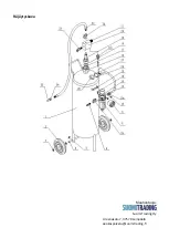
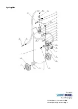
Part List  

Part  

Description  

Q'TY     Part  

Description  

Q'TY  

1  

Storage Tank  

1  

15  

Tank Bracket  

1  

2  

Wheel  

2  

16  

Hex Nut  

1  

3  

Washer ¢12  

4  

17  

O-Ring (¢35 x 3.1mm) 

1  

4  

Wheel Shaft  

1  

18  

Pickup Tube  

1  

5  

R-Pin ¢2 

2  

19  

Bushing (M42 x 2 – 1/2”)  

1  

6  

Male Coupler 1/4"  

1  

20  

Media Regulator  

1  

7  

ON OFF Valve M/F 1/4”  

2  

21  

Media Flow Control  

1  

8  

Regulator  

1  

22  

Media Hose Outlet  

1  

9  

Pressure Gauge  

1  

23  

Safety Valve  

1  

10  

Socket Head Cap Screw  

2  

24  

Nozzle Coupler  

1  

11  

Quick Disconnect Fitting  

2  

25  

Ceramic Discharge Nozzle  

1  

12  

Air Hose (350mm)  

1  

26  

Combination gasket 33  

1  

13  

Compression Nut  

1  

27  

Plug M33X2  

1  

14  

Bracket  

1  

28  

Soda mouth M33X2  

1  

Summary of Contents for 101604278

Page 1: ...teen asentamista ja k ytt Ohjeiden noudattamatta j tt minen voi aiheuttaa vakavan loukkaantumisen PID OHJE TALLESSA Yleisi turvaohjeita K yt tuotetta vain puhtailla suojalaseilla l k yt tulen l hettyv...

Page 2: ...bonaatti ruokasooda Asennus ja k ytt ohje Asennus Poista laite varovasti pakkauksestaan ja noudata asennusohjeita Katso asennuskaaviot 1 Aseta py r n akseli 4 s ili n 1 takajalkojen reikien l pi Aseta...

Page 3: ...ksesi sit Vinkkej Pid puhallusaine kuivana M rk n se tukkii virtauskanavat Jos virtauskanava tukkeutuu irrota nostoputki 18 ja keraaminen suutin 25 ja puhdista ne Jos puhallusaineen m r v hennee huoma...

Page 4: ...R j ytyskuva Maahantuoja Suomi Trading Oy Areenakatu 7 37570 Lemp l asiakaspalvelu suomitrading fi...

Page 5: ...sanvisningarna noggrant f re installation och anv ndning Underl tenhet att g ra detta kan leda till allvarliga skador SPARA MANUALEN S kerhetsf reskrifter Anv nd produkten endast med rena skyddsglas g...

Page 6: ...s och bruksanvisningar Montering Ta f rsiktigt bort enheten ur f rpackningen och f lj sedan installationsanvisningarna Se installationsdiagrammen 1 F r hjulaxeln 4 genom h len p tankens 1 bakben Place...

Page 7: ...ringsmedel Tips H ll bl stringsmedlet torrt Fuktigt bl stringsmedel t pper till fl det Om fl det t pps till ta d loss lyftr ret 18 och det keramiska munstycket 25 och reng r dem Om m ngden av bl strin...

Page 8: ...Spr ngskiss Import r Suomi Trading Oy Areenakatu 7 37570 Lemp l asiakaspalvelu suomitrading fi...

Page 9: ...before installation and use Failure to do so may result in serious injury SAVE THIS MANUAL General Safety Information Use this product only in clean working areas Do not use near the fire or in explo...

Page 10: ...Assembly Carefully remove the tool from the package and following the steps to install refer to the assembly diagram 1 Insert the wheel shaft 4 through the holes on the back legs of the storage tank...

Page 11: ...adjust the media flow rate Turning left decreases the flow rate and turning right to increases the flow rate Tips The media must be kept dry Provided the media is wet it will easily cake and block the...

Page 12: ...Assembly Diagram Imported by Suomi Trading Oy Areenakatu 7 37570 Lemp l asiakaspalvelu suomitrading fi...

Reviews: