Page 10
Installing Impression Rail
™
Express
Open Mid-Rail Level Panels
Dia. #8
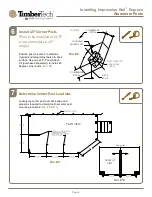
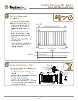
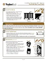
Install Foot Blocks
For openings greater than 4', install foot blocks
under center of bottom rail
(Dia. #8)
• Slide foot block under bottom rail and mark.
• Install two deck screws at location of foot
block, install foot block over screws.
• Using (1) - #8x3/4” self drilling screw, secure
the foot block to bottom rail, from the outside
of the panel so the screw will not be visible
from the deck surface.
(Dia. #9)
5
Dia. #9
#8 x 3/4" self-
drilling screws
Locate
Foot Block
Foot
Block
Install Foot
Block over 2x
deck screws
Important Note:
The top snap covers should snap firmly onto the aluminum railing channels.
Do not use a hammer.
The top rails will
snap by applying pressure from one end to the other. If you’re having issues snapping on the covers, check the clips
to ensure that they are bottomed out into the aluminum railing channels.
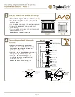
Foot Blocks must be installed BEFORE
installing Top Rail Snaps.
Dia. #10
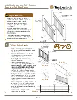
Install Top Rail Snaps
• Snap top rail snap over the unpunched H-channel until properly seated.
(Dia. #10)
TIP:
Roll the Top Rail Snap in place to avoid scratching the posts and put weight
down to get to the “second” snap.
NOTE: Do not install top snaps yet if lighting wires will be run through top rails.
6
3" POST DETAIL
3" X 3"
POST CAP
MOUNTING
STRUCTURE
4X BASE
MOUNTING
SCREWS
3" POST
BASE
RAIL PANEL CLIP DETAIL
RAIL PANEL
BOTTOM RAIL
WALL MOUNT
2X WALL
MOUNTING
SCREWS
IMPRESSION
WALL MOUNT
WALL MOUNT DETAIL
2X WALL MOUNTING
SCREWS
MOUNTING
STRUCTURE
BOTTOM RAIL
WALL MOUNT
2X WALL
MOUNTING
SCREWS
POST
H-CHANNEL
RAIL PANEL
CLIP
4X #8 X 3/4"
TEK SCREWS
2" POST DETAIL
CROSSOVER
BRACKET
4X BASE
MOUNTING
SCREWS
MOUNTING
STRUCTURE
2" POST
2" POST
BASE
2" BASE
SKIRT
SHEET 2 OF 2
PROPRIETARY AND CONFIDENTIAL
THE INFORMATION CONTAINED IN THIS DRAWING IS THE SOLE PROPERTY OF UltraLox.
ANY REPRODUCTION IN PART OR AS A WHOLE WITHOUT THE WRITTEN PERMISSION OF UltraLox IS NOT PERMITTED.
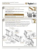
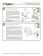
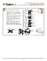
Wall Mounts (optional)
Use Wall Mounts if attaching level railing panels to
structural surfaces instead of posts.
• One Top Rail Wall Mount and two Bottom Rail Wall
Mounts are required to attach one Open Mid-Rail
panel to a structural surface.
(Dia. #11)
• Measure and mark locations on structural surface for
placement of three wall mounts.
(Dia. #5 & #12)
• Attach wall mounts to structural surface.
NOTE:
Wall mounting screws are dependent on the
type of structural surface. Consult a professional if
unsure of proper mounting screws.
• Continue installation of rail panels
7
Dia. #12
ISOMETRIC VIEW
BOTTOM RAIL
WALL MOUNT
(PART NUMBER VARIES
BY COLOR)
IMPRESSION
WALL MOUNT
(PART NUMBER VARIES
BY COLOR)
2.25
2.50
IMPRESSION
TOP RAIL
(PART NUMBER VARIES
BY LENGTH AND COLOR)
SHEET 1 OF 2
PICKET RAIL WITH OPEN MID-RAIL,
3" POSTS, 2" CENTER POST, WALL MOUNTED
PROPRIETARY AND CONFIDENTIAL
THE INFORMATION CONTAINED IN THIS DRAWING IS THE SOLE PROPERTY OF UltraLox.
ANY REPRODUCTION IN PART OR AS A WHOLE WITHOUT THE WRITTEN PERMISSION OF UltraLox IS NOT PERMITTED.
PART REFERENCE
(1X) TOP RAIL
WALL MOUNT
(2X) BOTTOM RAIL
WALL MOUNT
Dia. #11

