


TL/TN 775 M
achiNe
i
NiTiaL
S
eT
-U
p
G
Uide
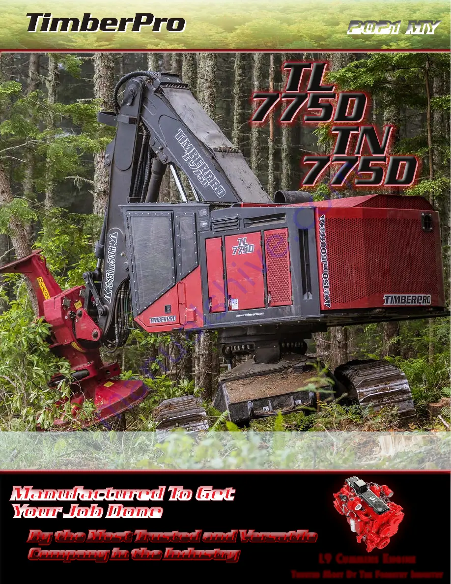
Manufactured To Get
Your Job Done
Manufactured To Get
Your Job Done
By the Most Trusted and Versatile
Company in the Industry
By the Most Trusted and Versatile
Company in the Industry
2021 MY
2021 MY
L9 C
ummins
E
nginE
T
rusTEd
m
osT
B
y
T
hE
F
orEsTry
i
ndusTry
L9 C
ummins
E
nginE
T
rusTEd
m
osT
B
y
T
hE
F
orEsTry
i
ndusTry
TL/TN 775 M
achiNe
i
NiTiaL
S
eT
-U
p
G
Uide
TL/TN 775 M
achiNe
i
NiTiaL
S
eT
-U
p
G
Uide


