


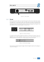
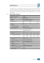
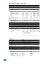
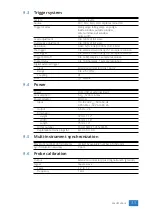


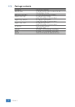


Front panel
7
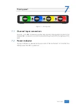
Figure 7.1: Front panel
7.1
Channel input connectors
The CH1 – CH4 BNC connectors are the main inputs of the acquisition system. The
isolated BNC connectors are not connected to the ground of the Handyscope HS6
DIFF.
7.2
Power indicator
A power indicator is situated at the top cover of the instrument. It is lit when the
Handyscope HS6 DIFF is powered.
Front panel
27
Summary of Contents for Handyscope HS6 DIFF Series
Page 1: ...Handyscope HS6 DIFF User manual TiePie engineering...
Page 6: ......
Page 21: ...Figure 3 15 over compensated Introduction 17...
Page 22: ...18 Chapter 3...
Page 25: ...Figure 4 3 Driver install Finished Driver installation 21...
Page 26: ...22 Chapter 4...
Page 32: ...28 Chapter 7...
Page 44: ...TiePie engineering Handyscope HS6 DIFF instrument manual revision 2 27 February 2020...


