


Pag. 10 / 20
TSol503 Manual V2.0
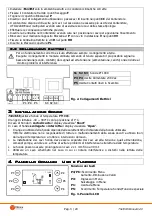
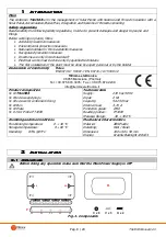
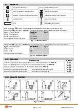
•
Install
TSol503
only in dry ambient and in correct climatic conditions
•
Fix the Box with fixing points
F
•
Take away the lid that cable-block
P
•
Insert the connecting cables through cablethrough
C
that are in the points
CC
of the Box
•
The box has 8 outputs for the cables: if more inputs are necessary
USE multipolar cables but put together only cables of the same type
•
Do the electrical connections
•
Put the controller in the Box and put the cable in order to facilitate the insertion
•
Block cable through the cable-block
P
with screws
V
in points
VV
•
Fix the controller through screws
H
in points
HH
•
Insert the plate
PL
2.2
2.2
2.2
2.2
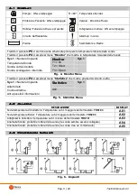
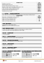
Electrical Connections
Electrical Connections
Electrical Connections
Electrical Connections
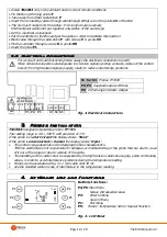
For a correct and safe functioning make always the electrical connections to earth
Make ordered connections and separate low tension signals (probes, contacts, cables of the control
board) from high tension signals (supply, loads) to reduce interference problems
S1 S2
S3
Probes PT1000
P3 P4
Supplied outputs 230 Vac
P5
In Exchange Contacts Output
Fig. 2. Electrical Connections
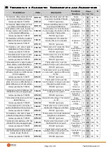
3
3
3
3
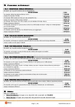
Probes Installation
Probes Installation
Probes Installation
Probes Installation
TSol503
manages temperature probes
PT1000
.
The reading range is -40 ÷ 300°C with precision of 1°C.
If the probe is in
short-circuit
the display shows “
Short
”
If the probe is
unconnected
or
broken
the display shows “
Open
”.
•
The probe’s range depends on the declared probe’s characteristics.
TiEmme elettronica is not responsible for damages or malfunctioning of the probe that are due to a use
of it out of the range or due to a break of the cable.
•
The installing of the cables must be separated by the high tension cables like supply, pump commands,
valves, in order to avoid interference problems during the temperature reading.
•
Probes can be extended with a 2 x 1 mm cable until 30 mt
•
Use the shielded cable in case of interference in the temperature reading.
4
4
4
4
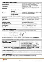
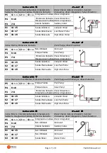
KeyBoard Use and Functions
KeyBoard Use and Functions
KeyBoard Use and Functions
KeyBoard Use and Functions
Button’s functions:
P4/P6
=Run Menu
Values Increase/decrease
P3
= Enter in Menu
Save in Menu
P1
= Exit Menu
P5
= Probes’ Temperature Scroll / Special Function
Fig. 3. LCD Panel
1
2
3
4
5
6 7
8
9 10 11 12 13
14 15 16 17 18 19
L N
Lo N Lo N
N
.O
.
N
.C
.
C
O
M
P3 P4
P5
LINE
230 Vac
S1 S2 S3
P1
P2
P3
P4
P5
P6
Lun 10.30
H
S
T1=80°


