


Pag. 20 / 44
DMAN802000066-SY250 Idro 4/8 Buttons Manual
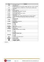
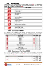
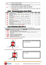
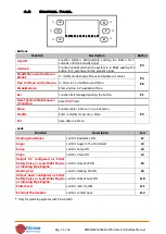
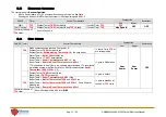
3.3.11
Outputs Test Menu (TP12)
Menu that allows to test the Outputs (and the connected loading) with the system in
Off
state.
Submenu
Description
To.01
Auger Test
To.02
Output V2 Test
To.03
Combustion Fan Test
To.04
Heating Resistance Test
To.05
Pump Test
To.06
Valve Test
To.15
Auxiliary Output Test
The Outputs, if enabled, will stop after 30 seconds.
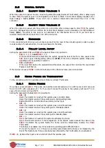
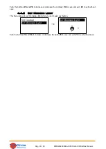
During the Combustion Fan Test, the display shows the set value [Volt] or [RPM] and the RPM of the fan
detected by the encoder (if is present): so it is possible to create a conversion table [RPM] / [Volt] to use for
the passage from encoder mode
P25
=1
to not encoder mode
P25
=0 in case of encoder breakage.
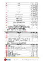
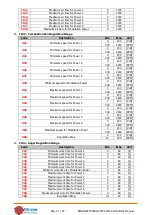
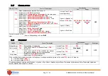
3.3.12
Extinguishing Thermostats Menu (TP13)
This Menu is the list of settings for each Combustion Power of the Exhausting Temperature under which,
after the Pre-Extinguishing time
T14
,
the system goes in Extinguishing for no flame (
Er03
). These values
occur with the
Th03
Thermostat.
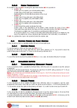
Code
Description
Min
Max
Unit
Th35
Power 1
5
900
[°C]
Th36
Power 2
5
900
[°C]
Th37
Power 3
5
900
[°C]
Th38
Power 4
5
900
[°C]
Th39
Power 5
5
900
[°C]
Th40
Power 6
5
900
[°C]
Th43
Modulation Power
5
900
[°C]
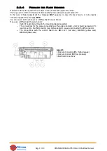
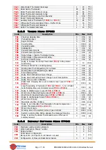
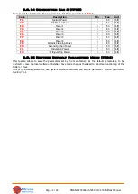
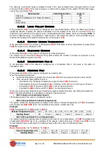
3.3.13
Primary Air Flow Sensor Menu (TP16)
Menu to set the Air Flow Regulator parameters; all parameters are referred to the current recipe: it has 4
Submenu:
1.
FL01 - Enables
Code
Description
Min
Max
Unit
A24
0
=Regulator disabled;
1
= Combustion Fan speed regulation;
2
=Combustion fan speed regAuger;
3
=Auger On
time regulation;
4
=Auger+Combustion fan speed regulation;
5
=Air Flow Sensor not installed
0
5
[nr]
A25
0
=Nothing to do if a regulation error occurs;
1
=in case of
regulation error, the regulator has been reset and restart
regulation;
2
=in case of regulation error the regulator is
disable
0
2
[nr]
A31
0
=The regulator comes back on the last output;
1
=The
regulator always works on the last output
0
1
[nr]
T19
Waiting time for stabilisation of regulation
5
900
[s]
T20
Waiting time for out of range regulator
10
900
[s]
T80
Waiting time for first regulation
0
900
[s]
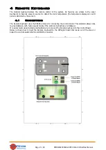
2.
FL02 - Air Flow Regulation Range
Code
Description
Min
Max
Unit
FL20
Minimum air flow in Check Up
0
2000
-
FL22
Minimum air flow for Power 1
0
2000
-
FL23
Minimum air flow for Power 2
0
2000
-
FL24
Minimum air flow for Power 3
0
2000
-
FL25
Minimum air flow for Power 4
0
2000
-
FL26
Minimum air flow for Power 5
0
2000
-
FL27
Minimum air flow for Power 6
0
2000
-
FL30
Minimum air flow for Modulation Power
0
2000
-
FL40
Maximum air flow
0
2000
-


