background image

4

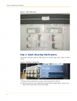
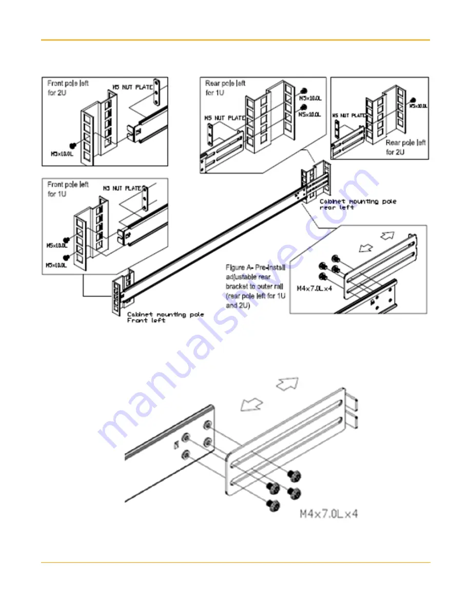
Step 2: Attach Mounting Rail Brackets


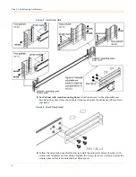
Figure 5

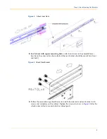
Install Outer Rails

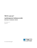
5.

For Cabinet with round mounting holes

: Attach and screw in the adjustable rear 

bracket to the outer rail as shown below (the rear bracket should be movable in front 
and back).

Figure 6

Attach Rear Bracket

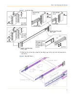
6.

Follow the orientation specified below to install the outer rail and rear bracket with 
screws and nut plates on the cabinet. Tighten the screws (as show in 

Figure 6

) after the 

whole outer rail set is mounted to the cabinet posts. 

Summary of Contents for LogLogic LX 1020

Page 1: ...TIBCO LogLogic Log Management Intelligence LMI Hardware Installation Guide Software Release 5 3 1 August 2012 ...

Page 2: ...LogLogic are either registered trademarks or trademarks of TIBCO Software Inc and or subsidiaries of TIBCO Software Inc in the United States and or other countries All other product and company names and marks mentioned in this document are the property of their respective owners and are mentioned for identification purposes only THIS SOFTWARE MAY BE AVAILABLE ON MULTIPLE OPERATING SYSTEMS HOWEVER...

Page 3: ...fy the following parts are available in the kit Table 1 Appliance Kit Components Item Qty Part Number Description 1 1 N A LogLogic Appliance 2 2 403 0002 00 Power cords Note LX820 Appliance has only 1 power cord 3 1 706 0063 00 Rail Kit 4 1 403 0014 00 Null modem cable DB9 F F 6 feet 5 1 100 0712 01 Documentation Supplemental CD 6 1 100 0725 01 Pre ship FQC Checklist 7 1 100 0736 01 Packing list R...

Page 4: ... chassis and rails with a side view of cabinet with one 2U system is shown below Figure 2 Side View of the Appliance 1 Remove the two identical main rails and the inner rails from the box 2 Attach inner rails to chassis either left or right side by using M4x4 0L screws Use 4 screws for 1U and 3 screws for 2U on each side ...

Page 5: ...bracket to the outer rail as shown below the rear bracket should be movable in front and back Figure 4 Attach Rear Bracket 4 Follow the orientation specified below to install the outer rail and rear bracket with screws and nut plates on the cabinet Tighten the screws as show in Figure 4 after the whole outer rail set is mounted to the cabinet posts ...

Page 6: ...bracket to the outer rail as shown below the rear bracket should be movable in front and back Figure 6 Attach Rear Bracket 6 Follow the orientation specified below to install the outer rail and rear bracket with screws and nut plates on the cabinet Tighten the screws as show in Figure 6 after the whole outer rail set is mounted to the cabinet posts ...

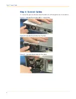
Page 7: ...5 Step 2 Attach Mounting Rail Brackets Figure 7 Install Outer Rails 7 Slide the chassis into the cabinet by inserting inner rails to the outer rail mounted in the cabinet Figure 8 Slide the Chassis ...

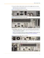
Page 8: ...ct Cables 1 Connect the power cables located at the back side of the Appliance as shown below Figure 9 Connected Power Cable LX820 1 Power Cable Figure 10 Connected Power Cables for 1U system Figure 11 Connected Power Cables for 2U system ...

Page 9: ... up with Console Connect one end of the Null modem cable located at the back of the Appliance and attach the other end to a laptop or terminal device for example HyperTerminal or puTTY Note This step is required only when you are setting up the Appliance using the Console If you are setting up with a Browser skip this step and go to Step 4 Power up the Appliance Figure 14 Connected Null modem cabl...

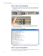
Page 10: ...utton for 2U system 2 Wait for about 3 to 5 minutes for system to boot up During this time you can see various messages appearing on the screen Once the system boots up the screen displays the following prompt Figure 18 Appliance Booting Process Completed Congratulations You have successfully installed the LogLogic Appliance Step 5 Log into the Appliance For instructions on how to log in to the Ap...

Page 11: ...Logic family of products Sorted by Appliance family every model is described Contents LX Product Family 10 ST Product Family 14 MX Product Family 18 Note All LogLogic 2U Appliances come with mounting slides that you can use to mount to a 19 inch enclosed equipment rack Hardware such as brackets and screws are provided to secure the Appliances to the 19 inch equipment rack ...

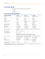
Page 12: ...degrees C Derate maximum temperature by 1 degree C per 300 meters above sea level Relative Humidity 20 80 non condensing 19 Rack Mount Chassis 1U 1U 2U Chassis Mounting Rail kit provided Rails adjust 28 to 31 and attach to front and rear of rack or cabinet Caution Rails cannot be properly mounted if adjusted to under 28 Chassis W x H x D 17 5 x 1 75 x 21 inches 44 50 x 4 45 x 53 30 cm 17 25 x 1 75...

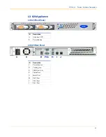
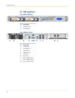
Page 13: ... LX 820 Appliance LX 820 Front Panel LX 820 Rear Panel ID Description A Attention LED B Power Button ID Description C Power Source D Cooling Fan E USB Ports x4 F Video Port G Serial Port H Eth 2 Port I Eth 0 Port J Eth 1 Port A B C D E F G H I J ...

Page 14: ... 1020 Rear Panel ID Description A Attention LED B Power Button ID Description C Cooling Fan D Power Source E Alarm Reset F USB Ports x2 G Video Port H Serial Port I Eth 3 and Eth 2 Ports J Eth 1 and Eth 0 Ports K L Eth 5 and Eth 4 Ports A B C D E F G H F I J K L ...

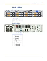
Page 15: ... 4020 Front Panel LX 4020 Rear Panel ID Description A Attention LED B Power Button ID Description C Power Module D Power Source E Alarm Reset F USB Ports x2 G Video Port H Serial Port I Eth 3 Eth 2 Ports J Eth 1 Eth 0 Ports K Eth 4 Eth 5 Ports A B C D E F G H I J K F ...

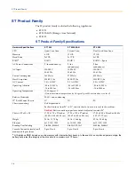
Page 16: ...g Temperature 10 35 degrees C Derate maximum temperature by 1 degree C per 300 meters above sea level Relative Humidity 20 80 non condensing 19 Rack Mount Chassis 1U 1U 2U Chassis mounting Rail kit provided Each rail adjusts from 28 to 31 and attaches to front and rear of rack or cabinet Caution Rails cannot be properly mounted if adjusted to under 28 Chassis W x H x D 17 25 x 1 75 x 27 inches 43 ...

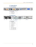
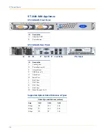
Page 17: ... Panel ST 1020 Rear Panel ID Description A Attention LED B Power Button ID Description C Cooling Fan x2 D Power Source x2 E Alarm Reset F USB Ports x2 G Video Port H Serial Port I Eth 3 and Eth 2 Ports J Eth 1 and Eth 0 Ports K L Eth 5 and Eth 4 Ports A B C D E F G H F I J K L ...

Page 18: ...e Distances Types ID Description A Attention LED B Power Button ID Description C Cooling Fan D Power Source x2 E Alarm Reset F USB Ports x2 G Video Port H Serial Port I Eth 3 Port J Eth 2 Port K Eth 1 Port L Eth 0 Port FC Fibre Channel 1 2 Cable Type and Distance meters Rate OM1 OM2 OM3 2Gbps 150 300 500 4Gbps 70 150 380 8Gbps 121 50 150 A B ...

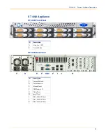
Page 19: ... 4020 Front Panel ST 4020 Rear Panel ID Description A Attention LED B Power Button ID Description C Power Module D Power Source E Alarm Reset F USB Ports x2 G Video Port H Serial Port I Eth 3 Eth 2 Ports J Eth 1 Eth 0 Ports K Eth 4 Eth 5 Ports A B C D E F G H I J K F ...

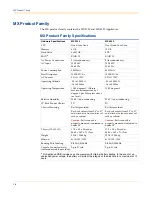
Page 20: ...80 non condensing 20 80 non condensing 19 Rack Mount Chassis 2U 2U Chassis Mounting Rail kit provided Each rail adjusts from 28 to 31 and attaches to front and rear of rack or cabinet Caution Rails cannot be properly mounted if adjusted to under 28 Rail kit provided Each rail adjusts from 28 to 31 and attaches to front and rear of rack or cabinet Caution Rails cannot be properly mounted if adjuste...

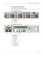
Page 21: ...s MX3020 Appliance MX 3020 MX 4020 Front Panel MX 3020 MX 4020 Rear Panel ID Description A Attention LED B Power Button ID Description C Power Module D Power Source E Alarm Reset F USB Ports x2 G Video Port H Serial Port I Eth 3 Eth 2 Ports J Eth 1 Eth 0 Ports K Eth 4 Eth 5 Ports A B C D E F G H I J K F ...

Page 22: ...20 MX Product Family ...

Page 23: ...ery Safety Caution Danger of explosion if battery is incorrectly replaced Replace only with the same or equivalent type recommended by the manufacturer Discard used batteries according to the manufacturer s instructions ...

Page 24: ...22 Battery Safety ...
Reviews: