background image

DW-­‐DS1101   User   guide.      


DSP   Wireless   Inc.   ©   2013   All   Rights   Reserved.      


www.dspwi.com


         V1.0      


Setup/   status   button   -­‐   

The   Setup/   Status   Button   has   multiple   uses   depending   on   the   state   of   the   DW-­‐DS1101.   


Normal   operation   –   Used   to   turn   on   the   OLED   display   and   cycle   thru   the   system   setup   info   screens.   


Firmware   upgrade   –   see   firmware   upgrade   manual.   


RS232   Port   -­‐      

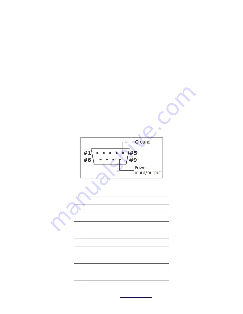
The   DW-­‐DS1101   features   a   multi-­‐channel   RS232   port.   Physically,   the   port   is   implemented   as   a   single   DB9M   
connector   with   three   output   lines,   three   input   lines,   and   the   ground.   
Internally,   the   DW-­‐DS1101   has   three   independent   serial   ports.   Each   serial   port   is   mapped   to   an   IP   PORT.      These   
are   the   Network   PORT   numbers   that   the   SA-­‐232D   App   uses   to   communicate   to   the   DW-­‐DS1101   serial   ports   (see   
   "SA-­‐232D   User   Manual").   
Each   of   the   three   ports   has   its   own   TX   and   RX   lines.   These   lines   are   implemented   in   hardware   and   can't   be   
"remapped".   The   following   table   shows   how   the   RX   and   TX   lines   are   connected   to   the   DB9M:   


Pin    Signal   

IP   PORT   (default)   

1   

Do   Not   Connect   


2   

Rx1   (input)   

40801   

3   

Tx1   (output)   

40801   

4   

Tx3   (output)   

40803   

5   

Ground   


6   

Rx3   (input)   

40803   

7   

Tx2   (output)   

40802   

8   

Rx2   (input)   

40802   

9   

Do   Not   Connect   


Summary of Contents for DW-DS1101

Page 1: ...DW DS1101 User guide DSP Wireless Inc 2013 All Rights Reserved www dspwi com V1 0 DW DS1101 User Guide v1 0 ...

Page 2: ... on when live Ethernet cable is plugged into the device The LED blinks whenever an Ethernet packet is received 100BaseT LED yellow is turned on when the device links with the hub at 100Mb The LED is off when the link is established at 10Mb If optional WiFi is installed then there are 5 Blue LEDs that indicate WiFi Rx signal strength OLED Display The 96x32 monochrome OLED display is used to display...

Page 3: ...three output lines three input lines and the ground Internally the DW DS1101 has three independent serial ports Each serial port is mapped to an IP PORT These are the Network PORT numbers that the SA 232D App uses to communicate to the DW DS1101 serial ports see SA 232D User Manual Each of the three ports has its own TX and RX lines These lines are implemented in hardware and can t be remapped The...

Page 4: ...t for more information on PoE Pin Signal 1 Tx 2 Tx 3 Rx 4 PoE 5 PoE 6 Rx 7 PoE 8 PoE Configure your Ethernet to RS232 adapter The DS1101 has a built in Web server for setup and configuration or you can use the DSPW PC setup and discovery tool DW DS1101 default IP address is 192 168 123 PC setup and discovery tool can be downloaded from the DSPW website Setup Configuration Discovery Reset to defaul...

Page 5: ...e is shipped with two mounting plates one for the installation on a DIN rail and one for mounting on the wall Both plates are secured onto the device using two supplied screws Wall mounting plate can be used to affix the DS110x to a wall in a semi permanent or permanent manner The diagram below shows important dimensions Not to Scale ...

Reviews: