Thurlby DSA524 Operating Manual Download Page 7


6

When  RUN/HOLD  is  set  to  HOLD,  the  remaining  3K  words  per 
channel  of  the  digitising  memory  are  set  to  zeroes  and  the 
disabled  functions  are  restored.  Pre-trigger  time  delay  is  limited 
to 10 divisions in FAST mode. 

In "roll" and "repeat" modes the RATE key is disabled. 

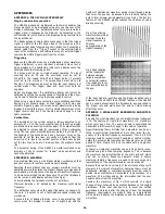
R14. ROLL MODE OPERATION 

In "roll" mode new data is written onto the right-hand side of the 
display  as  digitising  takes  place.  Thus  the  waveform  appears  to 
roll  across  the  screen.  The  operation  of  the  DSA524  in  "roll" 
mode (timebase speeds of 200msecs and below) is different from 
its operation in other modes in several respects: 
a) Triggering and Display Update Rate 
Because the waveform data is written continuously onto the dis-
play, it is not necessary to continually stop and restart the digiti-
sing  process.  Consequently  when  RUN  /HOLD  is  set  to  RUN, 
digitising takes place continuously and triggering is disabled. The 
RATE key is disabled. 
When  RUN/HOLD  is  set  to  HOLD,  triggering  is  enabled  for 
operation  via  the  SINGLE  key.  Pressing  SINGLE  commences  the 
"roll"  and  the  trigger  event  stops  it,  thus  the  waveform  data 
captured  is  entirely  pre-trigger  data.  Consequently  if  a  trigger 
occurs  immediately,  no  data  will  be  captured  unless  some  post-
trigger time delay has been set. When the trigger mode is set to 
AUTO,  triggering  occurs  immediately.  When  the  trigger  mode  is 
set  to  NORM,  triggering  occurs  synchronously  with  the  trigger 
signal. 
Because  in  "roll"  mode  the  trigger  stops  the  digitising  process 
instead of starting it, all the data in the digitising memory is pre-
trigger  data  unless  some  post-trigger  time  delay  has  been  set. 
Pre-trigger time delay is therefore not needed and is disabled. 
b) Display Window and Search mode 
Because the waveform data is written continuously to the screen 
as digitising takes place, the display shows the last part of the 4K 
digitising memory instead of the first part. Because the left hand 
edge of the display window is set in steps of 100 words, only 996 
words are displayed and the remaining 28 words are set to zero. 
SEARCH  can  only  be  selected  in  HOLD,  and  the  scan  window  is 
initially set fully to the right instead of fully to the left. 
c) Trace Controls 
When  in  roll  mode,  operation  of  any  of  the  trace  controls  (e.g. 
gain  variable)  will  effect  only  the  waveform  data  on  the  display 
which  was  captured  after  the  control  was  changed.  However, 
when  the  digitising  process  is  stopped,  the  new  trace  control 
values  will  be  applied  to  the  whole  of  the  contents  of  the 
digitising  memory  including  waveform  data  captured  before  the 
change was made. 
R15. REPEAT MODE OPERATION 
In  normal  mode  the  DSA524  can  digitise  a  waveform  at  up  to 
20MS  /s  digitising  rate,  equivalent  to  5usecs  per  division.  If  the 
waveform is repetitive (as opposed to being a single event) it can 
digitise the waveform repetitively, gradually building up the data 
in  the  digitising  memory.  This  mode  of  operation,  known  as 
"repeat" mode, is used for timebase speeds of 2usecs and above 
and provides equivalent digitising rates of up to 2GS /s (50nsecs 
per  div.).  The  operation  of  the  DSA524  in  repeat  mode  is 
different from its operation in normal mode in several respects: 
a) Triggering 
Repeat  mode  requires  a  synchronously  triggered  waveform, 
AUTO and LINE trigger modes are therefore disabled. Time delay 
is not available (neither pre nor post trigger). The trigger event is 
not  captured,  the  first  section  of  the  waveform  captured  starts 
350 nanoseconds after the trigger event. 
b) Display Update Rate 
Repeat  mode  involves  complex  manipulation  of  data  which  can 
take  several  seconds  per  digitisation.  The  display  update  rate 
varies  between  about  one  per  second  for  a  single  channel  at 
2usecs/div  to  one  every  10  seconds  for  both  channels  at 
50nsecs/div. The Rate key is disabled in repeat mode. 
R16. CURSOR MEASUREMENT 
Moveable  cursors  allow  accurate  measurements  of  voltage  and 
time  to  be  made  on  either  Trace  A  or  Trace  B  via  an  on-screen 
digital readout. 

To  select  cursor  measurement,  press  the  key  marked  ON/OFF 
within the numeric keypad. Cursors will appear on Trace A, and 
Trace  B  will  be  suppressed.  Pressing  the  key  marked  A/  B 
selects Trace B instead of Trace A. To turn cursor measurement 
off press the ON/OFF key again. 
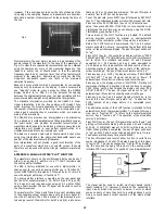


Cursor measurement. 


The  cursors  are  flashing  horizontal  lines  which  each  terminate 
at a point on the waveform. The reference cursor is on the left 
hand  side  of  the  screen,  the  delta  cursor  is  on  the  right  hand 
side.  The  measurement  is  made  between  the  two  lines.  The 
readout shows the voltage and time difference between the end 
of  the  reference  cursor  line  and  the  start  of  the  delta  cursor 
line.  The  cursors  are  moved  using  the  arrow  keys  marked  REF 
CURS and ∆ CURS respectively. 

R17. PROGRAM MODE 

The DSA524 can operate as a fully programmable instrument. It 
can  "learn"  individual  or  sequential  front  panel  settings,  store 
them  in  non-volatile  memory,  and  "replay"  them  on  demand. 
Up to 50 settings can be stored. 

Each  front  panel  setting  includes  the  state  of  every  key  and 
rotary control and the source of each trace waveform. Thus if a 
setting is "learned" which includes a trace recalled from a wave-
form store, that same store will be recalled again when the set-
ting  is  "re-played".  Thus  reference  waveforms  can  be  recalled 
automatically within PROGRAM mode. 

To "learn" one or more settings press the LEARN key, this turns 
on  learn  mode.  The  display  will  show  the  message  "NEXT 
POSITION = NN" for 3 seconds where NN is a number between 
01 and 50 corresponding to the position set when the unit was 
last used. 

To  store  a  front  panel  setting  in  this  position,  ensure  that  the 
front panel is set as required and press the SET/NEXT key. The 
display  will  show  the  message  "STORED  IN  NN"  followed  by 
"NEXT POSITION = NN + 1". To store another front panel set-
ting, reset the front panel as required and press the SET/NEXT 
key  again.  To  store  the  setting  in  any  other  memory  position, 
press the SET(NN) key followed by a two digit number between 
01 and 50. 

The  next  memory  position  can  be  checked  at  any  time  by 
pressing the LEARN key again. 

To  "replay"  one  or  more  settings  press  the  REPLAY  key,  this 
turns on replay mode. The display will show "NEXT POSITION = 
NN"  as  for  learn  mode.  To  replay  the  front  panel  setting  cor-
responding to this position press the SET/NEXT key. The display 
will show "REPLAYED FROM  NN" followed  by "NEXT POSITION 
=  NN  +  1".  Press  the  SET/NEXT  key  again  to  replay  this  next 
position.  To  replay  any  other  position  press  the  SETINN)  key 
followed by a two digit number between 01 and 50. 

The  next  memory  position  can  be  checked  at  any  time  by 
pressing the REPLAY key again. 

Whenever  the  front  panel  is  set  using  the  replay  mode  all  the 
rotary controls become inoperative. To make any rotary control 
operative again press the key directly to its right. (Press once if 
the lamp above the key is on, or twice if it is off.) 
To  exit  either  learn  or  replay  modes  press  the  LEARN  and 
REPLAY keys simultaneously. 


Summary of Contents for DSA524

Page 1: ...Thurlby DSA524 digital storage adaptor OPERATING MANUAL AND TUTORIAL V2 0 ...

Page 2: ...anual applies to units with a firmware level of 2 71 and above IT IS VERY STRONGLY RECOMMENDED THAT NEW USERS START BY FOLLOWING THE TUTORIAL INDEX Title Section Page REFERENCE SECTION Connecting an Oscilloscope R1 2 Setting up the Display R2 2 Front Panel Controls R3 2 Escape and Reset R4 2 Controlling Digitising R5 2 Timebase Setting R6 2 CH1 and CH2 R7 3 Digitising Memories R8 3 Trigger R9 3 Tr...

Page 3: ... NN the key will enter the number printed alongside it Note that when SHIFT or a function ending in NN is pressed the lamp marked ENTER will flash to indicate that one or more further key presses is required Any function that causes the ENTER lamp to flash can be cancelled by pressing that function key again Note that some of the functions including SET SCOPE automatically set the RUN HOLD functio...

Page 4: ... TRIGGER RATE ABOVE 1MHz and the DSA will beep to indicate that the timebase speed may need to be set faster R7 CH1 AND CH2 The two input channels are identical The input sensitivity is variable between 10V and 2mV per division The maximum bandwidth is 35MHz down to 20mV div 20MHz at 10mV div 10MHz at 5mV div and 5MHz at 2mV div The volts per division keys autorepeat if held The input coupling can...

Page 5: ... is automatically increased or decreased to maintain a constant time delay when the timebase speed is changed within a limit of 9 999 divisions maximum PRE there is no equivalent to pre trigger on a real time oscilloscope Pre trigger allows the part of the waveform which occurred before the trigger to be stored and observed The maximum pre trigger delay is 40 divisions Pressing either key shows th...

Page 6: ...unaffected R12 INDEXED WAVEFORM MEMORIES The DSA524 has sixteen 1K word memories for temporary or permanent storage of waveforms Each memory is identified by a two digit number from 01 through to 16 The memory is sup ported by trickle charged Ni Cad batteries which will remain charged for several months should the unit be left unpowered To store a waveform in an indexed memory obtain the required ...

Page 7: ...not captured the first section of the waveform captured starts 350 nanoseconds after the trigger event b Display Update Rate Repeat mode involves complex manipulation of data which can take several seconds per digitisation The display update rate varies between about one per second for a single channel at 2usecs div to one every 10 seconds for both channels at 50nsecs div The Rate key is disabled ...

Page 8: ...hen overflows could occur on the multiplied waveform The displayed waveform is limited to 4 25 divisions and conse quently 3 divs multiplied by 2 5 divs will be displayed as 4 25 divs instead of 7 5 divs The AxB function cannot operate while digitising is taking place Pressing the AxB key will set RUN HOLD to HOLD The function multiplies the traces exactly as they appear at the moment that the AxB...

Page 9: ... show baud rate 9600 for example Use the reference cursor keys keys 2 and 3 to increase or decrease the rate then press ESCAPE If the DSA is not connected to an oscilloscope the baud rate may be set directly using the FUNCTION NN key see Section R27 Note that as well as the options of 300 through to 38 400 there is a further option of IEEE This option is exclusively for use when the optional IEEE ...

Page 10: ...g SHIFT followed by RESET and with the signal generator being set to SINE 20kHz 5V pk pk INDEX TO THE TUTORIAL Page Equipment Required 10 Setting up the Equipment 10 First Steps 10 What to Expect 10 The Display Oscilloscope 10 Front Panel Controls 10 Getting out of Trouble 10 Part One The Basic Functions Controlling Digitising 10 Controlling the Input Channels 11 Controlling the Traces 11 Setting ...

Page 11: ...the display is made up of discrete steps waveforms do not look quite the same as they do with an analog oscilloscope The minimum level change between samples is one thirtieth of a division and even where the input signal level is constant the digitised level may vary slightly This variation is caused by noise on the signal noise in the input amplifiers or digitising noise in the ADC typically bit ...

Page 12: ...es on the screen and provide 4 25 divisions of adjustment Press the key marked HOME VAR to enable variable posi tion it is enabled when the lamp is off Try varying the position of the traces note that whereas OFFSET only affects the waveform when digitising is taking place PO SITION affects it at all times whether RUN HOLD is at RUN or HOLD Press the key again to home the trace position 2 The GAIN...

Page 13: ...els are on the ALT lamp illuminates for speeds of 10us div and faster and that the CHOP lamp illuminates for speeds of 20us div and slower CHOP indicates that both input channels are digitised together on opposite cycles of the sampling clock while ALT indicates that the input channels are digitised alternately CH2 followed by CH1 Thus if digitising is un triggered or if the input signals do not h...

Page 14: ... digitising memory captures 4096 words 40 96 divisions per channel The SEARCH key enables the whole of the digitising memory to be accessed It also provides digital magnification by ten using linear interpolation 1 Press SEARCH once the COMP compress lamp will illu minate and a filled bar will appear at the top of the screen for 3 seconds the filled bar represents the 4K of the memory Note that th...

Page 15: ... DSA reset and the generator set to SINE 20kHz 5V pk pk The DSA524 can average any number of readings from 2 up to 255 enabling large improvements to be made to the signal to noise ratio of noisy signals The average number is initially set to 16 1 Turn off Trace B and note the waveform amplitude on Trace A Then remove the trigger signal by setting the source to EXT The waveform should now be unsyn...

Page 16: ...volatile memory and replay them on demand Up to 50 settings can be stored Each front panel setting includes the state of every key and rotary control and the source of each trace waveform Thus if a setting is learned which includes a trace recalled from a wave form store that same store will be recalled again when the setting is re played Thus reference waveforms can be recalled automatically with...

Page 17: ...avoid aliasing Aliasing causes the apparent waveform frequency to be much lower than the real frequency Thus if the timebase is set too low an invalid display will result see Fig a To avoid aliasing the timebase must be set as follows Minimum time div 50 divided by the maximum cyclic signal frequency The difficulties occur when the signal frequency is unknown In this case it is safest to set a fas...

Page 18: ...isplay are plot ted using a level of 100mV div for both Y and X at a rate selec table as 1 2 5 or 10 seconds per division The pen lift signal is normally low to lift but can be inverted To set the plot rate press SHIFT key 8 followed by SET PLOT key 5 The oscilloscope display will show the present plot rate Press one of the REF CURS keys key 2 or 3 to select a new value then press ESCAPE If the DS...

Page 19: ...to have a buffer large enough to accept the data in one stream hand shaking will almost certainly be needed There are two basic types of handshaking hardware handshak ing and X ON X OFF handshaking Both types are provided on the DSA Hardware handshaking uses the RTS and CTS lines of the DSA When the RTS line is set to a 0 a positive voltage level the DSA is ready to receive data when it is set to ...

Page 20: ...trace starting at word N MAG N where N is a decimal number between 0 and 900 This sets the SEARCH function into Magnify mode with the trace starting at word N SROFF This turns any of the SEARCH modes off NORM SLOW or FAST This sets the display update rate ION or IOFF This sets sine interpolation on or off AON or AOFF This sets averaging on or off Example TMB 10uS AON SLOW CR For TRA or TRB the sec...

Page 21: ...ee previous section for an explanation of this command To load the data send the primary command MEM followed by a comma followed by one of the secondary commands listed below followed by a carriage return The secondary commands are as follows ACQ1 or AQU2 This loads the digitising memory of CH1 or CH2 4096 words must be sent TRA or TRB This loads the trace memory of Trace A or Trace B 1024 words ...

Page 22: ...n OSCILLOSCOPE DISPLAY SYSTEM Trace A Displays 1024 words from either CH1 or any indexed waveform storage memory Trace B Displays 1024 words from either CH2 or any indexed waveform storage memory Line Type Selectable as individual levels dots or joined to form a smooth line Update Rate Selectable between 50 per second and Run Mode one every 3 seconds continuous in roll mode OSCILLOSCOPE DISPLAY VE...

Page 23: ... dismantle it S4 FUSE REPLACEMENT The AC power fuse is mounted on the back panel within the AC line input socket housing To replace the fuse pull the clip in tray outwards The active fuse is at the back of the tray the front space is for a spare fuse The fuse must be replaced with a 500mA anti surge 20mm cartridge fuse A ceramic bodied HRC type should be used whenever possible S5 MAINTENANCE AND R...

Page 24: ...Thurlby Electronics Ltd New Road Burrel Road St Ives Huntingdon Cambs England Telephone 0480 63570 Fax 0480 64832 Telex 32475 ...

Reviews: