background image

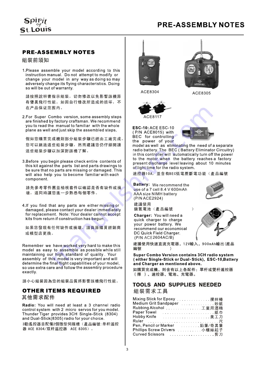
ACE 

8015

ACE 

2604AC/B

1

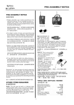
8.4V 600mAh AAA size

 ACE2924

Summary of Contents for Spirit of St. Louis 4323

Page 1: ...No 4323 Specifications Wing Span 39 3 8 1000mm Length 26 1 2 675mm Wing Area 226sq in 14 6dm Weight 16 8oz 470g Motor 370 Motor with 2 67 1 gearbox included 2 JE6719...

Page 2: ...Wing 5 Fuselage 6 Landing Gear 7 Tail 8 Servo 9 Cowl 10 Blance 11 Operation Check 12 Decal 13 Flying 17 Radio 19 Repair 20 Table of Contents Congratulations on the purchase of our finest D G A EP Park...

Page 3: ...ACE 8015 ACE 2604AC B 1 8 4V 600mAh AAA size ACE2924...

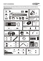
Page 4: ...izontal Tail Elevator Joiner Horizontal Tail Elevator AS6389 Vertical Tail Vertical Tail Rudder Square Guide AS6312S Snap on Control Horn Control Horn Locking Plate AS6390 Propeller Set 3 15mm Sink Sc...

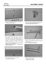
Page 5: ...cardboard then fully mix them with a small stick This 5 min Epoxy allows working time is only 3 minutes after mixing 3 The finished strut mounts are shown 4 Locate the wing threaded end and clevis th...

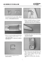
Page 6: ...Epoxy the pushrod support in the upper fuselage and thread the pushrods note the orientation of the holes in the suppport 11 Thread the clevis to prevent the pushrod sliding down from the fuselage 12...

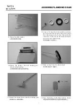
Page 7: ...nding gear 16 Locate E clip wheel rims and tire as photo shown Install the rim shown left in the photo first then snap on the E clip Next press the other rim CA the tire on the wheel and make sure the...

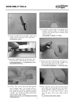
Page 8: ...f rudder at both sides and secured in place firmly 22 Trial fit the joiner in place next apply epoxy and glue it firmly in place It will be easier to bend two elevators then slide the joiner on the el...

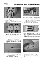
Page 9: ...ch of the electric speed controller Do not over tighten the screw as it may crush the Styrofoam 28 Use double sided tape to fix the ESC and Receiver inside the fuselage Connect all servo wires and con...

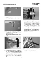
Page 10: ...of St Louis Next epoxy the cowl and dummy multi engine in place as shown 34 Install the propeller andspinner Itis necessary to secure the propeller firmly by a prop nut Always take great care on the m...

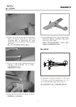
Page 11: ...fuselage with furnished ten 2 x 8 mm self tapping screws 36 Gently secure the main wing with furnished three 3 x 20 mm wood screws Note The mounting plate is underneath the wing mount area never push...

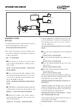
Page 12: ...d make sure the elevator moves up Check for the proper amount of throw and make sure the rudder and elevator are in neutral position when stick and trim levers are in the center 4 Hang the airplane an...

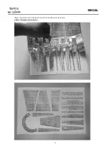
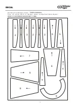
Page 13: ...13 DECAL Move the extra part of the decal to get the needed parts as shown...

Page 14: ...2 1 3 4 4 6 7 8 8 9 1 2 3 5 5 DECAL Each decal is numbered as shown 14 Note All arrows direct to fuselage always overlap about 2mm at the joint...

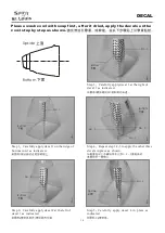
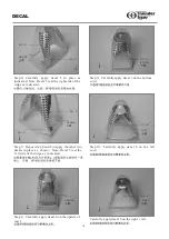
Page 15: ...ttom cowl as indicated Step 3 Carefully apply decal 3 at the right of decal 1 as indicated Step 4 Repeat step1 2 3 to apply the other three decals in place as shown Step 2 Carefully apply decal 2 at t...

Page 16: ...7 Repeat step 4 and 5 to apply the other two decals in place as shown Note Decal 5 is at the left side of the ridge as indicated 4 5 4 5 5 DECAL No 6 Upside Step 8 Carefully apply decal 6 on the upsi...

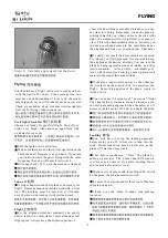
Page 17: ...by adding up elevator The plane should slow down even more and come in for gentle landing Don t add too much elevator too soon Walk over to the plane and turn off the ESC switch on the plane then the...

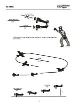
Page 18: ...Wind Direction Correct Incorrect Wind Direction Wind 3 ft Launch firmly into wind straight and level Do not throw upwards Landing FLYING 18...

Page 19: ...ck down Move the stick down and right RIGHT ROLL AND UP UP DOWN LEFT ROLL RIGHT ROLL NEUTRAL THE DIRECTION OF MOVEMENT AILERON AND ELEVATOR Elevator Rudder 5 8 15mm 5 8 15mm 1 2 12mm 1 2 12mm Control...

Page 20: ...ke sure the transmitter batteries are fresh c Make sureno one elseis operation onyour channel frequency inthe immediate vicinity REPAIR CONCLUSION REPAIR 3 If the plane does not fly properly a Make su...

Reviews: