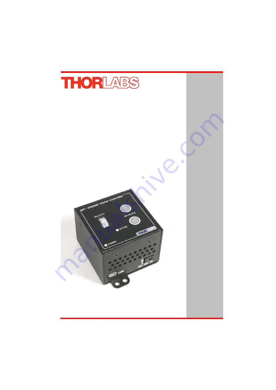
TST001T-Cube Stepper Motor Controller
User Guide
Original Instructions
Page 1: ...TST001 T Cube Stepper Motor Controller User Guide Original Instructions ...
Page 2: ...ons 13 3 2 3 Removing the Baseplate 14 3 3 Electrical Installation 15 3 3 1 Connecting a Motor 15 3 3 2 Using The TCH002 Controller Hub 15 3 3 3 Connecting To A Standalone Power Supply 16 3 4 Connect The Hardware 16 3 5 Select the Stage Type using APTConfig 17 3 6 Verifying Software Operation 19 3 6 1 Initial Setup 19 Chapter 4 Standalone Operation 21 4 1 Introduction 21 4 2 Front Panel Controls a...
Page 3: ...ng Loading a Settings file 36 5 10 Creating a Simulated Configuration Using APT Config 39 5 11 Stage Axis Tab 42 Chapter 6 Software Reference 43 6 1 Introduction 43 6 2 GUI Panel 43 6 3 Settings Panel 45 6 3 1 Moves Jogs Tab 45 6 3 2 Stage Axis Tab 48 6 3 3 Advanced Tab 51 Appendices Appendix A Rear Panel Connector Pinout Details 54 Appendix B Preventive Maintenance 55 Appendix C Specifications an...
Page 4: ...n when there is a risk of injury from electrical shock Warning Given when there is a risk of injury to users Caution Given when there is a risk of damage to the product Note Clarification of an instruction or additional information Warnings If this equipment is used in a manner not specified by the manufacturer the protection provided by the equipment may be impaired In particular excessive moistu...
Page 5: ...y flexible parameter set also supports operation with a wide range of third party stepper motors and associated stages actuators For convenience the footprint of this unit has been kept to a minimum measuring only 60mm x 60mm x 47mm 2 4 x 2 4 x 1 8 and with the facility to directly mount to the optical table close to the motorised device convenient when manually adjusting motor positions using the...
Page 6: ... described for both front panel and PC operation Tutorial sections Chapter 4 and Chapter 5 provide a good initial understanding on using the unit and reference section Chapter 6 covers all operating modes and parameters in detail 2 2 T Cube Controller Hub As a further level of convenience when using the new T Cube Controllers Thorlabs also offers the new T Cube Controller Hub TCH002 This product h...
Page 7: ...ed the APT server which provides all of the necessary APT system software services such as generation of GUI panels communications handling for multiple USB units and logging of all system activity to assist in hardware trouble shooting It is this APT server engine that is used by software developers to allow the creation of advanced automated positioning applications very rapidly and with great e...
Page 8: ...ed to allow multiple operating configurations to be created and easily applied For many users the APTUser application provides all of the functionality necessary to operate the APT hardware without the need to develop any further custom software For those who do need to further customise and automate usage of the Stepper Driver T Cube e g to implement a positioning algorithm this application illus...
Page 9: ...ttings have global effect such as switching between simulator and real operating mode associating mechanical stages to specific motor actuators and incorporation of calibration data The APTConfig utility is provided as a convenient means for making these system wide settings and adjustments Full details on using APTConfig are provided in the online help supplied with the utility Use of the APT Con...
Page 10: ...ed into a wide range of software development environments for use by client application developers Development environments supported include Visual Basic Labview Visual C C Builder HPVEE Matlab VB NET C NET and via VBA Microsoft Office applications such as Excel and Word Consider the ActiveX Control supplied for the APT stepper driver unit This Control provides a complete user graphical instrumen...
Page 11: ... System Architecture Diagram Refer to the main APT Software online help file APTServer hlp for a complete programmers guide and reference material on using the APT ActiveX Controls collection This is available either by pressing the F1 key when running the APT server or via the Start menu Start Programs Thorlabs APT APT Help Additional software developer support is provided by the APT Support CD s...
Page 12: ...parameters and modes The user can select multiple panel views displaying different information about a particular hardware unit The multitasking architecture ensures that the graphical control panels always remain live showing all current hardware activity Caution Some PCs may have been configured to restrict the users ability to load software and on these systems the software may not install run ...
Page 13: ...tepper Driver is shipped with a baseplate fitted ready to be bolted to a breadboard optical table or similar surface If desired the baseplate can be removed and the unit can be stood on rubber feet see Section 3 2 3 For multiple cube systems a USB controller hub TCH002 is available see Section 2 2 for further details Full instructions on the fitting and use of the controller hub are contained in h...
Page 14: ...g the unit to the baseplate Retain the bolts for future use if the baseplate is refitted 2 Invert the unit 3 Remove the backing paper from the rubber feet supplied taking care not to touch the exposed adhesive surface 4 Position the feet as desired then press and hold for a few seconds until the adhesive has bonded 5 The unit may now be used freestanding sitting on its rubber feet Detail A Detail ...
Page 15: ...ides power distribution for up to six T Cubes and requires only a single power connection from a separate supply unit TPS006 supplied by Thorlabs Further details are contained in handbook ha0146T T Cube Controller Hub supplied with the unit Shock Warning DO NOT PLUG A POWERED UP T CUBE INTO THE TCH002 USB CONTROLLER HUB Always ensure that all power is disconnected from the Stepper Driver T Cube AN...
Page 16: ...ontroller unit see Section 3 3 1 4 Connect the Controller unit to the power supply see Section 3 3 3 5 Connect the PSU to the main supply and switch ON 6 Connect the Controller unit to your PC Warning The unit must be connected only to a DC supply of 15V 1A regulated Connection to a supply of a different rating may cause damage to the unit and could result in injury to the operator Caution During ...
Page 17: ...stage type and axis with the motor controller Once this association has been made the APT server applies automatically suitable default parameter values on boot up of the software 1 Shut down all applications using the APT software components e g APT User or your own custom application 2 Run the APT Config utility Start Programs Thorlabs APT APT Config Note The USB cable length should be no more t...
Page 18: ...he side of the unit 5 In the Stage field select your actuator type e g ZST12 B from the list displayed 6 Click the Add Change Stage Association button The actuator type and serial number are added to the list in the main window as shown above 7 The server reads in the stage and controller information on start up Shut down the APTConfig utility and proceed to Section 3 6 to verify the software oper...
Page 19: ...i panel showing jog and ident buttons 2 Check that the actuator type and serial number associated in Section 3 5 are displayed in the GUI panel 3 Click the Ident button The LED on the front panel of the Stepper Driver T Cube flashes This is useful in multi channel systems for identifying which driver unit is associated with which GUI 4 Click the jog buttons on the GUI panel and check that the moto...
Page 20: ...al hardware units in order to emulate a set of real hardware This is a particularly useful feature designed as an aid to application program development and testing Any number of virtual control units are combined to build a model of the real system which can then be used to test the application software offline If using real hardware ensure that Simulator Mode is disabled If using a simulated set...
Page 21: ...and for more advanced operation adjustment of settings such as lead screw pitch and gearbox ratio allowing support for many different actuator configurations These parameters can be set via the APT Server software see Chapter 5 Furthermore when used with the extensive range of Thorlabs ZST motorised opto mechanical products many of these parameters are automatically set to allow out of the box ope...
Page 22: ... 3 for further details POWER LED Lit when power is applied to the unit This LED can be configured to flash when the Ident button is clicked on the APT Software GUI panel see Section 6 3 3 for further details 4 3 Potentiometer Operation The potentiometer slider is sprung such that when released it returns to it s central position In this central position the motor is stationary As the slider is mov...
Page 23: ...mode it is possible from the front panel to save the current position as the Go To Position value To save the current position as the Go To Position value press and hold the required button for 2 seconds 4 4 4 Jogging The front panel buttons can also be configured to jog the motor This mode of operation is enabled by setting the Button Mode parameter to Jogging on the Advanced settings tab see Sec...
Page 24: ...el please see Section 6 3 3 for more details Warning The default values applied by the software have been selected based on the type of stage or actuator connected and are applied automatically on start up Modify these values with caution as the risk of damage to the motor due to overheating is significant For the Thorlabs ZST series actuators the moving phase power is set to 60 at the factory Thi...
Page 25: ... Using the APT User Utility The APT User exe application allows the user to interact with any number of APT hardware control units connected to the PC USB Bus or simulated via the APTConfig utility This program allows multiple graphical instrument panels to be displayed so that multiple APT units can be controlled All basic operating parameters can be set through this program and all basic operati...
Page 26: ...is displayed in the Settings window See Section 5 11 and Section 6 3 for further details on the parameter values shown in the Settings display Fig 5 2 Stepper Driver T Cube Software GUI The APT User utility will be used throughout the rest of this tutorial to interface with the Stepper Driver T Cube ...
Page 27: ...ig 5 3 Stepper Driver T Cube GUI 1 Click the Home button Notice that the led in the button lights to indicate that homing is in progress and the displayed position for both channels counts down to 000 000 i e the home position 2 When homing is complete the Homed LED is lit as shown above See Appendix E Section E 2 2 for background information on the home position Note Homing can also be performed ...
Page 28: ...easured in real world units e g millimetres relative to the Home position 1 Click the position display Fig 5 4 Absolute Position Popup Window 2 Enter 3 0 into the pop up window 3 Click OK Notice that the position display counts up to 003 000 to indicate a move to the absolute position 3 00mm ...
Page 29: ...k the Settings button bottom right hand corner of the display to show the Settings panel Fig 5 5 Settings Panel Move Jogs Tab 2 Select the Move Jogs tab as shown in Fig 5 5 3 In the Moves field enter parameter values as follows Max Vel 0 25 Accn Dec 0 1 4 Click OK to save the settings and close the window 5 Any further moves initiated will now be performed at a maximum velocity of 0 25mm per secon...
Page 30: ...jog velocity while the button is held down 1 On the GUI panel click the Settings button to display the Settings panel Fig 5 6 Settings Panel Move Jogs Tab 2 Select the Move Jogs tab as shown in Fig 5 6 3 In the Jogs field enter parameter values as follows Velocity Profile Max Vel 0 25 Accn Dec 0 1 Operating Modes Jogging Single Step Stopping Profiled Step Distance 0 1 4 Click OK to save the settin...
Page 31: ...ion units per grid division and cursor position All units are displayed in real world units either millimetres or degrees The left hand display shows a circle which represents the current position of the motor associated with the specified controller absolute position data is displayed in the Chan Pos field The vertical divisions relate to the travel of the stage actuator associated with the Stepp...
Page 32: ...k the left hand mouse button to initiate the move Jog Mode When Jogging mode is selected the motors are jogged each time the left mouse button is clicked The Jog direction corresponds to the position of the cursor relative to the circle current motor position e g if the cursor is to the left of the circle the motor will jog left The Jog Step size is that selected in the Settings panel see Section ...
Page 33: ...be visited without user intervention For details on moving to absolute positions initiated by a mouse click see Section 5 7 1 From the Motor GUI Panel select Move Sequencer tab to display the Move Sequencer window Fig 5 8 Move Sequencer Window 2 Right click in the move data field to display the pop up menu Fig 5 9 Move Sequencer Pop Up Menu ...
Page 34: ...in the sequence The Dwell time is the time to wait in milliseconds Return if checked the system will move to the position specified in the Dist Pos field wait for the specified Dwell time and then return to the original position 4 Min Vel Acc and Max Vel the velocity profile parameters for the move The motor accelerates at the rate set in the Acc field up to the speed set in the Max Vel field As t...
Page 35: ...ng the data line s and selecting the appropriate option in the pop up menu shown below Fig 5 12 Pop Up Options 7 To run a single line of data right click the appropriate data and select Run from the pop up menu shown above 8 To run the entire sequence click the Run button shown below A Home move can also be performed from this panel by clicking the Home button Fig 5 13 Home and Run Buttons 9 To sa...
Page 36: ...ttings need to be changed the values can be saved to a Settings Group which can then be uploaded on subsequent start up When saving only those settings applicable to the graphical panels displayed will be saved For example if two motor panels are displayed then the settings for both panels will be saved together in a single set with a single name Settings are saved by association with the serial n...
Page 37: ...isplayed 5 Adjust the settings as necessary using the Settings button on each GUI panel 6 From the File menu select Save Any previously saved settings are listed in the main display To save the current settings under a new name enter a file name into the upper display area and click Save To save the settings under an existing name select a filename from the main display then click Save ...
Page 38: ...t recently used settings group Warning Settings should only be loaded automatically when the same hardware set up is being used for prolonged periods of time The Automatically load settings on Startup box must be unchecked before the system configuration can be changed e g to drive a different stage actuator This is particularly important when the system has previously been used in simulator mode ...
Page 39: ...an aid learning how to use the APT software and as an aid to developing custom software applications offline Any number of virtual control units can be combined to emulate a colection of physical hardware units For example an application program can be written then tested and debugged remotely before running with the hardware To create a simulated configuration proceed as follows 1 Run the APT Con...
Page 40: ... 5 4 In the Simulator field check the Enable Simulator Mode box The name of the most recently used configuration file is displayed in the Current Configuration window 5 In the Control Unit field select 1 Ch Stepper Driver T Cube TST001 ...
Page 41: ...ch physical APT hardware unit is factory programmed with a unique 8 digit serial number In order to simulate a set of real hardware the Config utility allows an 8 digit serial number to be associated with each simulated unit It is good practice when creating simulated configurations for software development purposes to use the same serial numbers as any real hardware units that will be used Althou...
Page 42: ...y when the ZST6 actuator was selected using the APTConfig utility in Section 3 5 The APT server automatically applied suitable defaults for the parameters on this tab during boot up of any client software such as APTUser These parameters should not be altered for pre defined Thorlabs stages and actuators selected using APT Config as it may adversely affect the performance of the stage For third pa...
Page 43: ...r utility Fig 6 1 Stepper Driver T Cube Software GUI Jog used to increment or decrement the motor position When the button is clicked the motor is driven in the selected direction at the jog velocity one step per click The step size and jog velocity parameters are set in the Settings panel see Section 6 3 Note The serial number of the Stepper Driver T Cube associated with the GUI panel the APT ser...
Page 44: ...ate a particular stage Calib File the calibration file associated with the specified channel See the APTConfig utility helpfile for more details on assigning and using calibration files Min Max V the minimum velocity at which a move is initiated and the maximum velocity at which the move is performed Values are displayed in real world units mm s or degrees s and can be set via the Settings panel s...
Page 45: ... Jog Settings Moves Velocity Profile Moves can be initiated via the GUI panel by entering a position value after clicking on the position display box see Section 5 4 or by calling a software function see the APTServer helpfile The following settings determine the velocity profile of such moves and are specified in real world units millimetres or degrees MinVel In current versions of software the M...
Page 46: ... received i e front panel button pressed or GUI panel button clicked There are two jogging modes available Single Step and Continuous In Single Step mode the motor moves by the step size specified in the Step Distance parameter If the jog key is held down single step jogging is repeated until the button is released see Fig 6 3 In Continuous mode the motor actuator will accelerate and move at the j...
Page 47: ...ist Settings to Hardware Many of the parameters that can be set for the Stepper Driver T Cube can be stored persisted within the unit itself such that when the unit is next powered up these settings are applied automatically This is particularly important when the driver is being used manually in the absence of a PC and USB link The Velocity Profile and Jogging parameters described previously are ...
Page 48: ... how to associate a stage and axis Once this association has been made the APT server will automatically apply suitable defaults for the parameters on this tab during boot up of the software These parameters should not be altered for pre defined Thorlabs stages selected using APT Config as it may adversely affect the performance of the stage For custom stage types not available using the APT Confi...
Page 49: ... to the Home position Velocity the maximum velocity at which the motors move when Homing For further information on the home position see Section E 2 2 Hardware Limit Switches The operation of the limit switches is inherent in the design of the associated stage or actuator The following parameters notify the system to the action of the switches when contact is made Select Rev Switch or Fwd Switch ...
Page 50: ...fitted with a gearbox Note The Steps Per Rev and Gearbox Ratio parameters together with the Pitch and Units parameters are used to calculate the calibration factor for use when converting real world units to microsteps However the Steps Per Rev parameter is entered as full steps not microsteps The system automatically applies a factor of 128 microsteps per full step The stepper motors used on the ...
Page 51: ...e holding Caution The Persist Settings functionality is provided to simplify use of the unit in the absence of a PC When the unit is connected to a PC and is operated via APTUser the default APTServer settings will be loaded at boot up even if the Persist Settings option has been checked Warning The default values applied by the software have been selected based on the type of stage or actuator co...
Page 52: ...ion is selected the Active LED is lit when the motor is moving It is recognised that in a light sensitive environment stray light from these LEDs could be undesirable Therefore it is possible to disable selectively one or all of the LED indicator modes described above by clearing the associated check boxes in the LED Indicator Modes field Button Control Settings The buttons on the front of the uni...
Page 53: ...hat when the unit is next powered up these settings are applied automatically This is particularly important when the driver is being used manually in the absence of a PC and USB link The potentiometer button and LED parameters described above are good examples of settings that can be altered and then persisted in the driver for use in absence of a PC To save the settings to hardware check the Per...
Page 54: ...e pin functions are detailed in Fig A 1 Notes Pull low to enable Fig A 1 MOTOR I O Connector Pin Identification Pin Description Pin Description 1 Ground 9 For Future Use 2 CCW Limit Switch 10 5V 3 CW Limit Switch 11 Enc A ve 4 Phase B ve 12 Enc A ve 5 Phase B ve 13 Enc B ve 6 Phase A ve 14 Enc B ve 7 Phase A ve 15 Channel Enable 8 For Future Use 5 10 11 15 6 1 ...
Page 55: ... if the equipment is operated with the covers removed Only personnel authorized by Thorlabs Ltd and trained in the maintenance of this equipment should remove its covers or attempt any repairs or adjustments Maintenance is limited to safety testing and cleaning as described in the following sections Warning Disconnect the power supply before cleaning the unit Never allow water to get inside the ca...
Page 56: ...ut 5 V Differential Encoder Feedback Bandwidth 500 kHz Position Counter 32 bit Operating Modes Position Velocity Velocity Profile Trapezoidal Motor Drive Connector 15 Way D Type Motor Drive Outputs Phase A B Quadrature Encoder QEP Input Single Ended Limit Switch Inputs Forward Reverse Common Return Encoder Supply 5 V Front Panel Controls Sprung Potentiometer Slider 4 Speed Bidirectional Velocity C...
Page 57: ...me Part Number Low Power Stepper Motor Drive 6mm travel Threaded Attachment ZST6 Low Power Stepper Motor Drive 6mm travel Barrel Attachment ZST6B Low Power Stepper Motor Drive 13mm travel Threaded Attachment ZST13 Low Power Stepper Motor Drive 13mm travel Barrel Attachment ZST13B Low Power Stepper Motor Drive 25mm travel Threaded Attachment ZST25 Low Power Stepper Motor Drive 25mm travel Barrel At...
Page 58: ...ntrol can be used to perform activities such as homing stages absolute and relative moves and changing velocity profile settings A brief summary of ech method and property is given below for more detailed information and individual parameter descriptiond please see the on line help file supplied with the APT server Methods DeleteParamSet Deletes stored settings for specific controller DisableHWCha...
Page 59: ...on Gets the current motor position returned by value GetPositionEx Gets the current motor position GetPositionEx_UncalibPosition Gets the current uncalibrated motor position returned by value GetPositionOffset Gets the motor position offset GetRelMoveDist Gets the relative move distance GetRelMoveDist_RelDist Gets the relative move distance returned by reference GetStageAxis Gets the stage type in...
Page 60: ...ocity Initiates a move at constant velocity with no end point SaveParamSet Saves settings for a specific controller SetAbsMovePos Sets the absolute move position SetBLashDist Sets the backlash distance SetDispMode Sets the GUI display mode SetHomeParams Sets the homing sequence parameters SetHWLimSwitches Sets the limit switch configuration settings SetJogMode Sets the jogging button operating mod...
Page 61: ...filed decelleration manner Properties APTHelp Specifies the help file that will be accessed when the user presses the F1 key If APTHelp is set to True the main server helpfile MG17Base will be launched DisplayMode Allows the display mode of the virtual display panel to be set read HWSerialNum specifies the serial number of the hardware unit to be associated with an ActiveX control instance ...
Page 62: ...les on both the rotor and stator For example with a 24 step motor such as that used in the ZST actuators positional increments steps of 15 degrees can be achieved by switching the coils If the current through one coil is increased as it is decreased in another the new rotor position is somewhere between the two coils and the step size is a defined fraction of a full step microstep The size of the ...
Page 63: ...profile reflecting the shape of the velocity vs time graph see Fig E 2 thereby driving the stage to its destination as quickly as possible without causing it to stall or lose steps The stage is ramped at acceleration a to a maximum velocity v As the destination is approached the stage is decelerated at a so that the final position is approached slowly in a controlled manner Fig E 2 Graph of a trap...
Page 64: ... stages can include stages that control the angle of a platform within a certain range although the movement of the platform is not really linear but angular Rotary stages can rotate indefinitely like a wheel Linear and rotary stages can contain microswitches that detect certain positions of the stage but they differ in the way these switches are used All linear stages have a ve limit switch to pr...
Page 65: ... a rotary stage is requested the answer will be reported as a number between 0 and 360 degrees measured in the positive direction from the Home position Fig E 4 Minimum and Maximum Positions E 2 5 Power Saving The current needed to hold a motor in a fixed position is much smaller than the current needed to move it When a stepper motor is at rest it is advisable to reduce the phase holding currents...
Page 66: ...om 10 to 20 mm is carried out as one simple move whereas a negative move from 20 to 10 mm first causes the stage to overshoot the target position and then move positively through a small amount Fig E 5 Backlash correction The particular stage selection will usually have this type of backlash correction enabled as its default mode of operation but it can be overridden if the overshoot part of the m...
Page 67: ...nd found to comply with the limits for a Class A digital device persuant to part 15 of the FCC rules These limits are designed to provide reasonable protection against harmful interference when the equipment is operated in a commercial environment This equipment generates uses and can radiate radio frequency energy and if not installed and used in accordance with the instruction manual may cause h...
Page 68: ... bin logo see Fig 1 sold to a company or institute within the EC currently owned by a company or institute within the EC still complete not disassembled and not contaminated Fig 6 1 Crossed out wheelie bin symbol As the WEEE directive applies to self contained operational electrical and electronic products this end of life take back service does not refer to other products such as pure OEM product...
Page 69: ... a public waste disposal site F 2 3 Ecological background It is well known that WEEE pollutes the environment by releasing toxic products during decomposition The aim of the European RoHS directive is to reduce the content of toxic substances in electronic products in the future The intent of the WEEE directive is to enforce the recycling of WEEE A controlled recycling of end of life products will...
Page 70: ...70 HA0141T Rev 7 Oct 2014 Chapter 6 ...
Page 71: ...erica Thorlabs Inc sales thorlabs com techsupport thorlabs com Europe Thorlabs GmbH europe thorlabs com France Thorlabs SAS sales fr thorlabs com Japan Thorlabs Japan Inc sales thorlabs jp UK and Ireland Thorlabs Ltd sales uk thorlabs com techsupport uk thorlabs com Scandinavia Thorlabs Sweden AB scandinavia thorlabs com Brazil Thorlabs Vendas de Fotônicos Ltda brasil thorlabs com China Thorlabs C...
Page 72: ...72 www thorlabs com ...