


27
T-Cube NanoTrak Autoalignment Controller
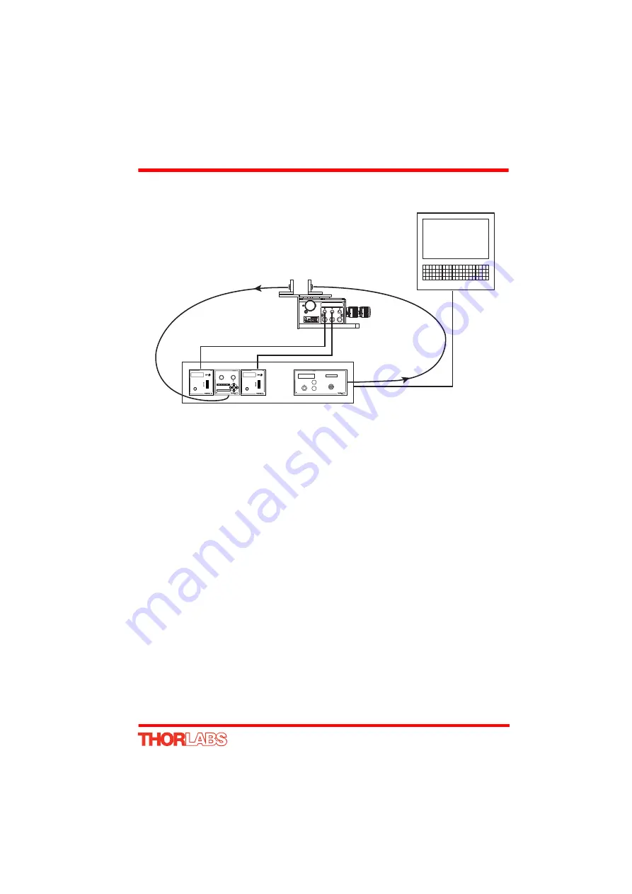
6) Install any mechanical components such as fiber holders etc. - see Fig. 5.2 for a
typical set up..
Fig. 5.2 Typical Set Up - Hub Operation
7) Connect the controller hub to the power supply - see Section 3.3.4.
8) Connect the PSU to the main supply and switch ‘ON’. The version number of the
embedded software is displayed on each Piezo unit during boot up. The software
version is useful when requesting technical support. The ident number of the
associated T-Cube bay on the hub is also displayed.
9) Connect the controller hub to your PC.
(
Note
. The USB cable should be no more than 3 metres in length. Communication
lengths in excess of 3 metres can be achieved by using a powered USB hub).
10)Windows
TM
should detect the new hardware. Wait while Windows
TM
installs the
drivers for the new hardware - see the Getting Started guide for more information.
11)Run the Kinesis software.
Start/All Programs/Thorlabs/Kinesis/Kinesis.
12)Click the ‘Settings’ button on GUI of the Piezo Driver fitted in bay 1. The Settings
panel is displayed.
Note
. To identify the piezo unit associated with a GUI panel,
click the ‘Ident’ button; the Power LED on the panel of the associated controller
flashes for a short period.
13)Make the following parameter settings, as shown in Fig. 5.3
Output Voltage Range -
Set the corresponding voltage for the piezo being
driven
, 75V, 100V or 150V.
Input Settings -
Select
So External Signal
PC
SAFETY
KEYSWITCH
POWER
mW
mA
dBm
MODE
OK
OUTPUT
HFB003
Fiber Holder
HFB003
Fiber Holder
MAX311
Flexure Stage
POWER
LATCH
MODE
LATCH/TRACK
SIGNAL
RANGE
1 2 3 4 5 6 7 8 9 101112
KPZ101
Piezo
Driver
KPZ101
Piezo
Driver
TNA001
NanoTrak
TLS001
Laser
Source
Piezo Controller
MENU
Piezo Controller
MENU


