


OTM211
Chapter 4: Operation
Rev A, October 7, 2015
Page 11
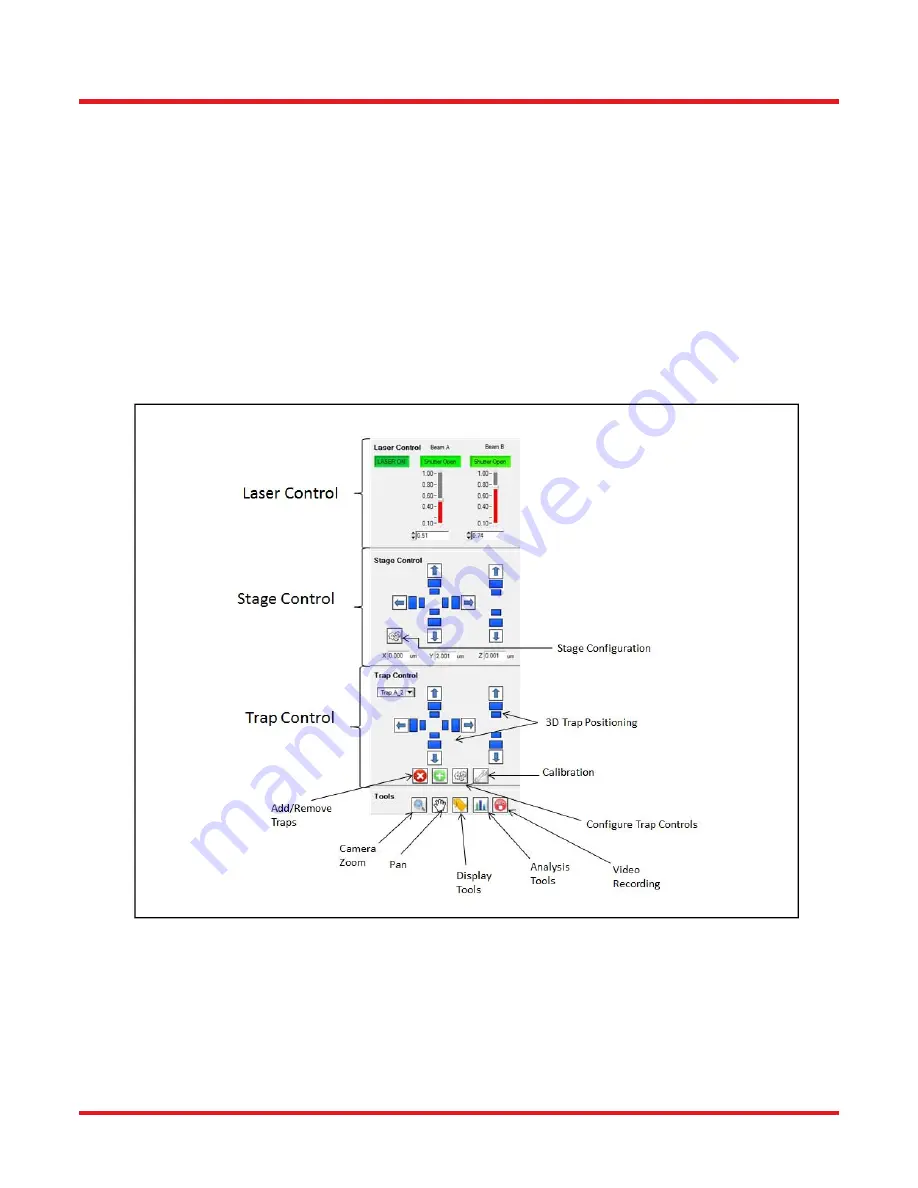
The main screen of the software contains two areas: the video image acquired from the camera on the left side and
controls for the system on the right side. The control sections consist of four segments: Laser, Stage, and Trap
Control as well as Tools.
In a typical trapping application a user will trap a particle by positioning the trap either by clicking on the camera
image or by using the adjuster buttons in the trap control section. Which trap is currently selected is indicated in the
drop-down list. If a new trap is added the currently selected beam path (A or B) will be used to add another time-
share trap location. The position of the new trap can be set by clicking on the camera image. The tool section allows
the user to select information which will be display for the traps on the camera display, such as the trap label and
position.
The speed and step size for the trap movement are adjustable and can be optimized, e.g. when switching between
different objectives.
The analysis tools depend on the system configuration and provide access to e.g. force spectroscopy measurement
or particle tracking.
Figure 8
OTM211 GUI Showing Controls
4.3. SDK
The OTM211 Tweezers System is supplied with a software development kit (SDK). The SDK gives access to all
features of the instrument, thus enabling the creation of custom, application-specific software. The SDK is provided
as a 64 Bit Windows dynamic link library (dll). Language bindings for C, National Instruments LabView and C# are
available. For details, please refer to the OTM211 Programmer’s Reference Manual.
Summary of Contents for OTM211
Page 1: ...OTM211 Optical Tweezer System User Guide...
Page 18: ...www thorlabs com...


