Rev F Apr 2019
Page 13
Chapter 4 Operation
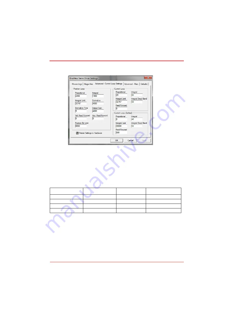
2) Click the Settings button on the GUI to display the Settings panel, then select the
‘Advanced’ tab.
Fig. 4.4 Advanced Control Loop Settings
3) Adjust the acceleration and PID settings to fine tune the control loop for your
application see Table 4.1 and Table 4.2 for more information.
4) After the parameter changes have been performed, click the ‘Persist Settings to
Hardware’ box, then click ‘OK’. This will ensure that the same parameter settings
will be loaded next time the unit is powered up - even in the absence of a PC.
Depending on the shape of the mass and the accelerations and velocities used the
values quoted above may require adjustment to provide optimum performance.
Table 4.1 Position Loop Parameter Adjustment Guidelines
Load Range(g)
Derivative
Derivative Time
Output Gain
0 to 250
4500
5
4000
250 to 500
5160
5
4660
500 to 750
5830
6
5330
750 to 900
6500
7
6000


