background image

Rev B Apr 2018

Page 28

Chapter 7 Software Reference

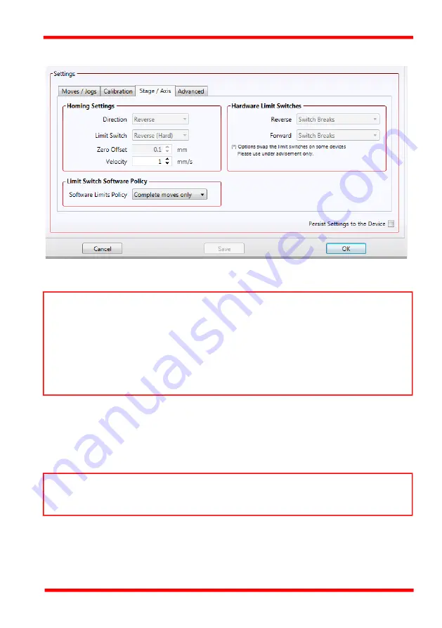
7.3.4 Stage/Axis Tab

Fig. 7.7   MLJ150 Stage - Stage/Axis Settings 

Homing Settings 

When homing, a  stage  typically  moves  in the reverse  direction, (i.e.   towards  the

reverse limit switch). The following settings allow support for stages with both Forward

and Reverse limits.

Direction

 - the direction sense that the motor moves when homing, either 

Clockwise

or 

Counter Clockwise

.

Limit Switch

 - The hardware limit switch associated with the home position, either

Ignore, 

Clockwise or  Counter Clockwise

.

Note

This  tab  contains  a  number  of  parameters  which  are  related  to  the  physical

characteristics of the particular stage being driven. They need to be set accordingly such

that a particular stage is driven properly by the system. 
For  MLJ150,  the  Kinesis  software  will  automatically  apply  suitable  defaults  for  the

parameters on this tab during boot up of the software and these parameters should not

normally  be altered  subsequently  as it  may  adversely  affect  the performance  of  the

stage. Descriptions are provided for information only.

Note

Typically,  the  following  two  parameters  are  set  the  same,  i.e.  both  Forward  or  both

Reverse.

Summary of Contents for MLJ150

Page 1: ...MLJ150 Motorized Lab Jack Kinesis User Guide Original Instructions ...

Page 2: ...4 RS232 USB Comms 11 4 5 Verifying Software Operation 12 Chaper 5 Standalone Operation 13 5 1 Introduction 13 5 2 Top Panel Controls and Indicators 13 5 3 Potentiometer Operation 14 5 4 Button Operation 14 Chaper 6 PC Operation 15 6 1 Introduction 15 6 2 Using the Kinesis Software 15 6 3 Homing Motors 16 6 4 Stopping the Stage 16 6 5 Changing Motor Parameters and Moving to an Absolute Position 17 ...

Page 3: ...ev B Apr 2018 Page 0 Appendices Appendix A Preventive Maintenance 32 Appendix B Specifications 33 Appendix C Stepper Motor Operation 35 Appendix D Regulatory 40 Appendix E Thorlabs Worldwide Contacts 42 ...

Page 4: ... parallelism while providing smooth quiet motion Integral limt switches prevent overdriving The large 148 mm x 131 mm 5 83 x 5 16 mounting platform supports up to 44 lbs 20 kg with a smooth vertical adjustment range of 2 50 mm Both the top and bottom plates offer a generous array of 1 4 20 M6 tapped holes and clearance slots for general mounting requirements Fig 1 1 MLJ150 Motorized Lab Jack The M...

Page 5: ...mponents that supply both a graphical user interface and a programmable interface Many such Controls are available for Windows applications development providing a large range of re usable functionality For example there are Controls available that can be used to manipulate image files connect to the internet or simply provide user interface components such as buttons and list boxes With the Kines...

Page 6: ...tions to be automated by a client application The instrument panel reflects the current operating state of the controller unit to which it is associated e g such as motor position Updates to the panel take place automatically when a user client application is making software calls into the same Control For example if a client application instructs the associated stage to move the progress of that ...

Page 7: ...with the controllers Fig 1 2 System Architecture Diagram Refer to the main Kinesis Software online help file for a complete programmers guide and reference material on using the Kinesis Controls collection This is available either by pressing the F1 key when running the Kinesis server or via the Start menu Start Programs Thorlabs Kinesis Kinesis Help 1 1 2 Software Upgrades Thorlabs operate a poli...

Page 8: ...here is a risk of injury to users Caution Given when there is a risk of damage to the product Note Clarification of an instruction or additional information Warning If this equipment is used in a manner not specified in the handbook the protection provided by the equipment may be impaired In particular excessive moisture may impair operation Spillage of fluid such as sample solutions should be avo...

Page 9: ...Work Surface 3 3 1 General When mounting the lab jack close to other equipment ensure that the travel of the moving platform is not obstructed If equipment mounted on the moving platform is driven against a solid object damage to the internal mechanism could occur The range of travel is 2 0 50 mm vertically Caution Once removed from its packaging the MLJ150 lab jack is easily damaged by mishandlin...

Page 10: ...orized Labjack 3 3 2 Mounting the Stage to the Work Surface The MLJ150 lab jack is mounted to the working surface by four M6 1 4 20 screws through the base as shown in Fig 3 1 Fig 3 1 Installation 4 Bolts M6 1 4 20 2 each side ...

Page 11: ... and the hardware and a communications error may be generated To minimize the possibility of this happening it is strongly recommended that any such modes that result in prolonged unresponsiveness be disabled before the software is run Please consult your system administrator or contact Thorlabs technical support for more details Caution Some PCs may have been configured to restrict the users abil...

Page 12: ...The PSU unit must be connected only to an earthed fused supply of 100 to 240V Use only the power supply supplied by Thorlabs other units may not be rated to the same current The unit is shipped to the UK Europe and the USA with the appropriate power plug already fitted When shipped to other territories the appropriate power plug must be fitted by the user Cable identification is as follows Brown L...

Page 13: ...tallation 7 WindowsTM should detect the new hardware Wait while WindowsTM installs the drivers for the new hardware see the Getting Started guide for more information Fig 4 1 Power and USB Connectors _ USB THORLABS CB74EX UK RS232 MLJ150 M 6 7 8 9 1 2 3 4 5 ...

Page 14: ... can be used without further set up The pin functions are detailed in in Fig 4 2 Fig 4 2 RS232 Connector Pin Identification Pin Description 1 Not Connected 2 TX controller input 3 RX controller output 4 Not Connected 5 Ground 6 Not Connected 7 Clear to Send CTS Input 8 Request to Send RTS Output 9 Not Connected Note When using the RS232 Port or a virtual comms port via USB communication is achieve...

Page 15: ...e control keypad flashes This is useful in multi channel systems for identifying which driver unit is associated with which GUI 3 Click the jog buttons on the GUI panel and check that the associated stage moves The position display for the associated GUI should increment and decrement accordingly Note If the Kinesis software does not recognise the unit switch OFF the power but leave the kinesis so...

Page 16: ...x C 5 2 Top Panel Controls and Indicators Fig 5 1 Front Panel Controls and Indicators MOVE Controls These controls allow all motor moves to be initiated Jog Buttons Used to jog the motors and make discrete position increments in either direction left button up right button down see Section 6 6 for more details on jogging Slider Potentiometer Used to drive the motor at a pre defined speed in either...

Page 17: ...ute position moves can be measured see Section 6 3 and Section C 2 2 for further information on the home position To initiate a Home move press and hold both buttons for 2 seconds 5 4 2 Jogging The front panel buttons can also be used to jog the motor The jogging parameters for the buttons are taken from the Jog parameters on the Move Jogs settings tab see Section 7 3 Note The two buttons and the ...

Page 18: ...t panels to be displayed so that multiple units can be controlled All basic operating parameters can be set through this program and all basic operations such as motor moves can be initiated Parameter settings can be saved which simplifies system set up whenever the software is run up Fig 6 1 Typical Kinesis User Screen 1 Run the Kinesis software Start All Programs Thorlabs Kinesis Kinesis Warning...

Page 19: ...displayed position for both channels counts down to 000 000 i e the home position 2 When homing is complete the Homed LED is lit as shown above See Appendix C Section C 2 2 for background information on the home position 6 4 Stopping the Stage The drive channel is enabled and disabled by clicking the Enable button on the GUI panel The green indicator in the button center is lit when the drive chan...

Page 20: ...e velocity settings relate to the maximum velocities at which a move is performed and the acceleration at which the motor speeds up from zero to maximum velocity 1 On the GUI panel click the Move arrow to show the Settings panel Fig 6 3 Move Settings Panel 2 Enter the required absolute position and or parameter values 3 To move to the position entered click the arrow 4 Click Apply to save the para...

Page 21: ... single step jogging is repeated until the button is released see Fig 7 3 In Continuous mode the motor actuator will accelerate and move at the jog velocity while the button is held down 1 On the GUI panel click the word Jog to display the Settings panel Fig 6 4 Jog Settings Panel 2 Make parameter changes as required 3 Click Apply to save the settings and close the window click Reset to return to ...

Page 22: ...gs e g max velocity jog step size etc can be changed as required Other settings e g PID parameter values cannot be changed so easily When the Kinesis Server is run up and the stage acuator association made suitable default settings are loaded and these values have been chosen to provide safe performance in the majority of applications However for applications where these settings need to be change...

Page 23: ...on in millimetres or degrees of the motor The motor must be Homed before the display will show a meaningful value i e the displayed position is relative to a physical datum the limit switch Move Opens the settings window so that position data and velocity parameters can be entered see Section 6 5 Moves are performed using the current velocity parameters which can be changed in the same panel The p...

Page 24: ... jog velocity parameters can be changed by clicking Jog or the small down arrow to display the settings panel Homed Not Homed lit when the motor has not been Homed since power up When the home button is clicked the caption changes to Homed and the LED flashes while the home move is being performed The LED is lit green once the move is complete End Stop lit when a limit switch is activated i e the ...

Page 25: ...ge can be stored persisted within the unit itself such that when the unit is next powered up these settings are applied automatically This is particularly important when the driver is being used manually in the absence of a PC and USB link The Velocity Profile and Jogging parameters described previously are good examples of settings that can be altered and then persisted in the driver for use in a...

Page 26: ...tiated by using the Jog keys on the GUI panel see Section 6 6 or the Jog Buttons on the front panel of the unit Step Size The distance to move when a jog command is initiated The step size is specified in real world units mm or degrees dependent upon the stage Mode The way in which the motor moves when a jog command is received i e front panel button pressed or GUI panel button clicked There are t...

Page 27: ...y at which to perform a move Acceleration the rate at which the velocity climbs from zero to maximum and slows from maximum to zero Velocity Parameters Moves can be initiated via the GUI panel by entering a position value after clicking on the position display box see Section 6 5 or by calling a software function see the KinesisServer helpfile The following settings determine the velocity profile ...

Page 28: ...ete these parameters will then remain unchanged until the next move begins The specific move profile created by the system depends on several factors such as the profile mode and profile parameters presently selected and other conditions such as whether a motion stop has been requested Profile This field is used to set the profile mode to either Trapezoidal or S curve In either case the velocity a...

Page 29: ...e axis at the specified Bow Index BI until the maximum acceleration A is reached The axis continues to accelerate linearly Bow Index 0 through segment 2 The profile then applies the negative value of Bow Index to reduce the acceleration to 0 during segment 3 The axis is now at the maximum velocity V at which it continues through segment 4 The profile then decelerates in a similar manner to the acc...

Page 30: ...points and these errors are stored as a look up table LUT The LUT is saved as a calibration file one file for each particular stage Whenever the stage is moved the LUT is consulted to ascertain the precise movement required to achieve the demanded position The use of a calibration file is optional Without it the repeatability and resolution of the stage are unaffected but no compensations are made...

Page 31: ...position either Ignore Clockwise or Counter Clockwise Note This tab contains a number of parameters which are related to the physical characteristics of the particular stage being driven They need to be set accordingly such that a particular stage is driven properly by the system For MLJ150 the Kinesis software will automatically apply suitable defaults for the parameters on this tab during boot u...

Page 32: ...nt in the design of the associated stage or actuator The following parameters notify the system to the action of the switches when contact is made Select Reverse or Forward as required then select the relevant operation Switch Makes The switch closes on contact Switch Breaks The switch opens on contact Ignore Absent The switch is missing or should be ignored Limit Switch Software Policy Note The m...

Page 33: ... the motor does not overheat When moving these phase currents are boosted to provide sufficient motor torque and minimise the possibility of stalling missed steps The moving phase powers are set automatically by the unit and cannot be adjusted The Resting Power is entered as a percentage of full power Note The default values applied by the software have been selected based on the type of stage or ...

Page 34: ...position to which the motor will move when the top button is pressed Right Lower Button Pos The position to which the motor will move when the bottom button is pressed Drive Array Velocities These parameters relate to the velocity for moves initiated by the DRIVE bar graph Each specifies a velocity to apply when the associated bar is clicked These settings are applicable in either direction of pot...

Page 35: ... codes then re enabled In the event of a breakdown or malfunction of the product please contact Thorlabs Tech Support Contact details are contained in Appendix E Warning The equipment contains no user servicable parts There is a risk of electrical shock if the equipment is operated with the covers removed Only personnel authorized by Thorlabs Ltd and trained in the maintenance of this equipment sh...

Page 36: ...mm 3 9 from Center of Platform 5 N m 44 in lb Max Velocity 3 0 mm sec All Loads Resolution 0 8 nm Unidirectional Repeatability Software Corrected 10 µm Bidirectional Repeatability System Backlash 50 µm Deck Parallelism 150 µm Over Full Travel Range Pitch Roll Error over 50 mm Travel 500 µrad Accuracy 30 µm Lead Screw Pitch 1 0 mm Motor Specifications Step Angle 1 8 Step Accuracy 5 Rated Phase Curr...

Page 37: ...8 Appendix B Specifications Page 34 Power 30 W Peak Dimensions W x D x H Extended 131 0 x 216 7 x 115 mm 5 16 x 8 53 x 4 53 Retracted 131 0 x 216 7 x 65 0 mm 5 16 x 8 53 x 2 56 Weight 2 47 kg 5 4 lbs Parameter Value ...

Page 38: ... are shown above in reality there are numerous tooth like poles on both the rotor and stator The result is that positional increments steps of 1 8 degrees can be achieved by switching the coils i e 200 steps per revolution If the current through one coil is increased as it is decreased in another the new rotor position is somewhere between the two coils and the step size is a defined fraction of a...

Page 39: ...e stage to its destination as quickly as possible without causing it to stall or lose steps The stage is ramped at acceleration a to a maximum velocity v As the destination is approached the stage is decelerated at a so that the final position is approached slowly in a controlled manner Fig C 2 Graph of a trapezoidal velocity profile C 2 Positioning a Stage C 2 1 General Whenever a command is rece...

Page 40: ...le Linear stages can include stages that control the angle of a platform within a certain range although the movement of the platform is not really linear but angular Rotary stages can rotate indefinitely like a wheel Linear and rotary stages both contain microswitches that detect certain positions of the stage but they differ in the way these switches are used All linear stages have a ve limit sw...

Page 41: ...ositions are conventionally set to 0 and 360 degrees respectively When the position of a rotary stage is requested the answer will be reported as a number between 0 and 360 degrees measured in the positive direction from the Home position Fig C 4 Minimum and Maximum Positions C 2 5 Power Saving The current needed to hold a motor in a fixed position is much smaller than the current needed to move i...

Page 42: ...ion in Fig C 5 a positive move from 10 to 20 mm is carried out as one simple move whereas a negative move from 20 to 10 mm first causes the stage to overshoot the target position and then move positively through a small amount Fig C 5 Backlash correction The controller has this type of backlash correction enabled as its default mode of operation but it can be overridden if the overshoot part of th...

Page 43: ...t harmful interference when the equipment is operated in a commercial environment This equipment generates uses and can radiate radio frequency energy and if not installed and used in accordance with the instruction manual may cause harmful interference to radio communications Operation of this equipment in a residential area is likely to cause harmful interference in which case the user will be r...

Page 44: ...Motorized Labjack Page 41 ETN041703 D03 D 2 CE Certificate ...

Page 45: ...ontact Thorlabs for more information Waste treatment is your own responsibility End of life units must be returned to Thorlabs or handed to a company specializing in waste recovery Do not dispose of the unit in a litter bin or at a public waste disposal site For technical support or sales inquiries please visit us at www thorlabs com contact for our most up to date contact information USA Canada a...

Page 46: ...www thorlabs com ...

Reviews: