background image

Tel: (800) 521-8467                                        Email

[email protected]

                                          https://thorbroadcast.com 


10 


10 


Figure-4 

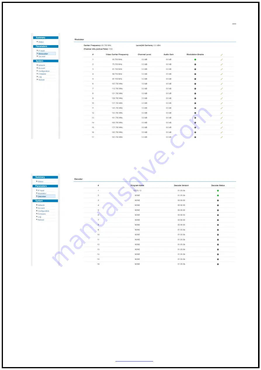
Parameters → Decoder: 

This function is to monitor status of decoding. It displays the interface as Figure-5. 


Figure-5


Parameters → OSD: 

Clicking  “OSD”,  it  displays  the  interface  where  to  configuration  the  OSD  parameters 

(Figure-6) 


Summary of Contents for H-IP-32RF

Page 1: ...User Manual 1 IP to Analog Modulator H IP 32RF ...

Page 2: ...ithout the written permission of the copyright owner The contents of this document are subject to revision without notice due to continued progress in methodology design and manufacturing THOR shall have no liability for any error or damage of any kind resulting from the use of this document Copy Warning This document includes some confidential information Its usage is limited to the owners of the...

Page 3: ... Specifications 1 1 3 Appearance and Illustration 2 Front panel Illustration 2 Rear Panel Illustration 2 Chapter 2 Installation Guide 4 2 1 Acquisition Check 4 2 2 Installation Preparation 4 3 1 Login 7 3 2 Operation 7 Chapter 4 Troubleshooting 15 Chapter 5 Packing list 16 ...

Page 4: ...jacent or adjacent carriers output within 400MHz Support Web based Network management 1 2 Specifications Input Interface rate 2 GE ports max 64 IP input Max 840Mbps for each GE input Stream UDP UDP RTP 1 7 packets FEC SPTS MPTS Transport Protocol UDP RTP Unicast and multicast IGMP V2 V3 Packet Length 188 204 Bytes Decoding Parameters Video HEVC H 265 H 264 AVC Level 4 1 HP MPEG 2 MP HL Audio MPEG ...

Page 5: ...4 43 SECAM under development Video signal to noise ratio 60dB Network Interface Management 1 x 100 Base T Ethernet RJ 45 Data 2 x 1000 Base T Ethernet RJ 45 Protocol IEEE802 3 Ethernet RTP ARP IPv4 TCP UDP HTTP IGMPv2 v3 Others Image resolution up to 1080i CNR 60 dB after internal combining SNR 53 dB after internal combining Sampling frequency 48 44 1 32 Output volume adjustment 0 100 General Demi...

Page 6: ...l sales thorfiber com https thorbroadcast com 3 3 Rear Panel Illustration 1 NMS network management port 2 Power Indicator 3 Grounding 4 AC Power Socket 5 Power switch 6 Data Input 7 RF output port 8 RF test port 5 6 7 8 4 3 ...

Page 7: ...lation Preparation When users install device please follow the below steps The details of installation will be described at the rest part of this chapter Users can also refer rear panel chart during the installation The main steps of the installation include Checking the possible device missing or damage during the transportation Preparing relevant environment for installation Installing H IP 32RF...

Page 8: ...nd device s frame should be no less than 25mm2 Machine Hall Space When user installs machine frame array in one machine hall the distance between 2 rows of machine frames should be 1 2 1 5m and the distance against wall should be no less than 0 8m Machine Hall Floor Electric Isolation Dust Free Volume resistivity of ground anti static material 1X10⁷ 1X10¹⁰ Grounding current limiting resistance 1M ...

Page 9: ...t of rear panel and the power switch is on the left of front panel User can plug one end of the power cord to the socket and insert the other end to AC power When the device solely connects to protective ground it should adopt independent way say share the same ground with other devices When the device adopts united way the grounding resistance should be smaller than 1Ω Caution Before connecting p...

Page 10: ...nd use ping command to confirm they are on the same network segment For instance the PC IP address is 192 168 99 252 we then change the device IP to 192 168 99 xxx xxx can be 0 to 255 except 252 to avoid IP conflict Launch the web browser an input the device IP address in the browser s address bar and press Enter It displays the Login interface as Figure 1 Input the Username and Password Both the ...

Page 11: ...put and then select one channel to parse It will display the interface where users can choose the programs to output and program info re set Figure 3 Configure Input Area and Output Area with buttons in Operation Area Instructions are as below To add input channel which come from Data 1 or Data 2 or Data Module front panel To edit the input channel To delete the input channel To delete all inputs ...

Page 12: ...grams To select all the output programs To parse programs time limitation of parsing input programs Program Modification The multiplexed program information can be modified by clicking the program in the output area For example when clicking it triggers a dialog box as below where users can set the program info Parameters Modulator Clicking Modulator it will display the interface as Figure 4 where...

Page 13: ...thorbroadcast com 10 10 Figure 4 Parameters Decoder This function is to monitor status of decoding It displays the interface as Figure 5 Figure 5 Parameters OSD Clicking OSD it displays the interface where to configuration the OSD parameters Figure 6 ...

Page 14: ...adcast com 11 11 Figure 6 Figure 7 Select to configure logo caption Browse and select the Logo which has been created Click here to confirm the LOGO you selected Enter your text here Select the text color and background color Move your caption on the screen ...

Page 15: ...the interface as Figure 9 where to set network parameters Figure 9 System Account Click Account it displays the screen as Figure 10 where to set the login Username and password for the web NMS Set data port IP address To modify IP input address Select channel 1 2 3 32 apply the logo insertion or you can select all to apply all channels ...

Page 16: ...figuration it displays the screen as Figure 11 where to set your configurations for the device Figure 11 System Firmware Click Firmware it displays the screen as Figure 12 where to update firmware for the device Figure 12 System Log Click Log it displays the screen as Figure 13 where to check the Log Select areas ...

Page 17: ...521 8467 Email sales thorfiber com https thorbroadcast com 14 14 Figure 13 System Reboot Click Reboot it displays the screen as Figure 14 where to check the Reboot Figure 14 To select Kernel log and System Log ...

Page 18: ...tion for the heat sink on the rear panel and other heat sink bores if necessary Checking the input AC voltage within the power supply working range and the connection is correct before switching on device Checking the RF output level varies within tolerant range if it is necessary Checking all signal cables have been properly connected Frequently switching on off device is prohibited the interval ...

Page 19: ...Tel 800 521 8467 Email sales thorfiber com https thorbroadcast com 16 16 Chapter 5 Packing list H IP 32RF 1 pc Power Cord 1 pc Grounding Cable 1 pc ...

Reviews: