background image

35

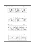
IC501 One Chip – Pin 19 – B

2Vpp

                      20 

µ

  s

IC501 One Chip – Pin 20 – G                                                                            2Vpp

                       20 

µ

 s

Q702 Collector Pin

7.6Vpp

          20

µ

Q701 Base Pin

10Vpp

          20

µ

 s

Summary of Contents for RCA CR29TF420

Page 1: ...nc Printed in U S A Trademark s Registered Marca s Registrada s Page Number Adjustments Onscreen Display 9 Circuit Decription 21 Disassembly 5 IC Pin Descriptions 15 Remote Control 14 Replacement Partlist 37 Schematics InterconnectDiagram 46 AV Switch 47 Micro Controller 48 One Chip 49 Power Supply 50 Stereo Decoder and Audio Output 51 Tuner 52 Vertical and Horizontal Output 53 Video Output 54 Ser...

Page 2: ...ase the buttons Press POWER To certify that the initialization was success executed it will appear the following message ILLUSTRATION 1 3 2 OSD Adjustment Service Mode To obtain the SERVICE MENU do the following procedure With the TV set unplugged from the AC Power keep pushed the button Volume up in the front panel and plug it After 20 seconds release Volume up and press Power Press Volume up and...

Page 3: ...E POINT ADJUST 3 4 AGC Adjustment Apply a color bar pattern RF Input with 500µV signal Connect a DC Voltmeter in the AGC pin of the tuner Adjust AGC to Zero and measure the voltage V1 Adjust AGC so that the indication on the voltmeter be V1 1 0 2V 3 5 Stereo Adjustment For the adjustments proceed according to illustration 2 Adjust output indicated by A to tension equal to half of VCC plus 1V Adjus...

Page 4: ... line of the circle pattern in the half cut of the screen Return SBL from 1 to 0 value The image could be compressed or expanded Select VA item and set its value to adjust the size of the picture proportional height and width picture If necessary readjust SC item and set its value to adjust the Linearity acts in the top of the image and VA NOTE The SC and VA adjustments are interdependent they sho...

Page 5: ...in the for edges of the screen 3 8 FOCUS Adjustment Apply a Circle Pattern Philips signal at the antenna terminal Magic ORIGINAL Adjust Focus V potenciometer vertical for the better focus on the vertical lines in the center of the screen Adjust Focus H potentiometer horizontal for the better focus on the horizontal lines inthe center of the screen Check the focus on the areas indicated below and r...

Page 6: ...e Screen Grid Potentiometer fully counter clockwise 3 5 4 Short circuit C803 to Ground located in the CPT PCI and change the register VSD FROM 0 TO 1 for cutting Vertical Deflection and turn the Screen potentiometer gradually clockwise and set it to the point where a thin bright line begin to appear on CPT Remove the short circuit of C803 and change VSD FROM 1 TO 0 3 5 5 Check the White Balance an...

Page 7: ...switch in the front panel that turns on the 9V supply waking up the circuit The output voltages are controlled by the IC901 through the opto coupler feedback IC902 and a reference voltage given by IC903 The basic output voltages are 1 130 Volts for the horizontal circuit 2 18 Volts for audio output circuits 3 9 Volts for TV signal processor stereo decoder and AV circuits 4 5 Volts for microprocess...

Page 8: ...from 55 25 MHz to 801 25 MHz This device is controlled by I2C bus The IF output signal 45 75 MHz is connected to the IC501 through a SAW filter MF201 6 5 AV SWITCHES IC470 IC480 and surrounding components The external audio and video signals AV1 AV2 AV3 are selected by the Micro Controller using two output signals pin47 av2 and pin48 av1 IC101 The video signals are selected using IC480 LA7221 and ...

Page 9: ... provides output current to drive the yoke The input signals are vertical drive from the TV signal processor pin46 and 47 of IC501 Horizontal deflection circuit uses 15 7KHz signal HOUT_pin40 IC501 to drive the fly back transformer T701 and provides the output current to drive horizontal deflection coil yoke and others CTR voltages HV focus screen and etc The vertical deflection circuit has one pr...

Page 10: ...r cord from the AC source Remove the anode cap Disconnect the ground connector CM801 Remove the CRT PCB 2 3 Main PCB refer to figure 2 2 2 3 Disconnect the following connectors CM901 CM902 CM701 CM601 CM401 and CM402 Unlock the PCB from the cabinet both sides of the board Remove the Main PCB 2 4 CRT refer to figure 2 4 Remove the four 4 screws RemovetheCRT Note The REMOVAL OF THE ANODE CAP After t...

Page 11: ...6 ...

Page 12: ...7 ...

Page 13: ...8 ...

Page 14: ...OUT 19 BLUE OUTPUT GOUT 20 GREEN OUTPUT ROUT 21 RED OUTPUT BCLIN 22 INPUT OF BEAM CURRENT LIMIT VERTICAL PROTECTION RIN 23 OSD RED INPUT GIN 24 OSD GREEN INPUT BIN 25 OSD BLUE INPUT FBLANK 26 OSD BLANKING LUMIN 27 Y INPUT LUMOUT 28 Y OUTPUT B YOUT 29 B Y OUTPUT R YOUT 30 R Y OUTPUT B YIN 31 B Y INPUT R YIN 32 R Y INPUT REFO 33 SUB CARRIER REFERENCE OUTPUT XTAL1 34 NTSC CRYSTAL CONECTION XTAL2 35 P...

Page 15: ...PULSE INPUT FSCSEL 8 GROUND FSC 9 IDENTIFICAÇÃO DE SUB PORTADORA SYS2 10 INPUT OF SYSTEM IDENTIFICATION 2 SYS1 11 INPUT OF SYSTEM IDENTIFICATION 1 Y CVBS1 12 Y INPUT 1 AGND 13 GROUND Y CVBSout 14 Y OUTPUT OUTSEL 15 NOT CONNECTED Cout 16 CHROME OUTPUT 5 3 IC 601 TDA8351 SIGN PIN DESCRIPTION Idrive neg 1 NON INVERTING INPUT VCC 2 SUPPLY VOLTAGE 12V Vp 3 SUPPLY VOLTAGE 55V VCC 4 SUPPLY VOLTAGE 12V OU...

Page 16: ...2 NINV2 9 NON INVERTING INPUT 2 5 7 IC 901 TDA16846 SIGN PIN DESCRIPTION OTC 1 OFF TIME CIRCUIT PCS 2 PRIMARY CURRENT SIMULATION RZI 3 REGULATION AND ZERO CROSSING INPUT SRC 4 SOFT STAR AND REGULATION CAPACITOR OCI 5 OPTO COUPLER INPUT FC2 6 FAULT COMPARATOR 2 GND SYN 7 SYNCHRONIZATION INPUT NC 8 NOT CONNECTED REF 9 REFERENCE VOLTAGE AND CURRENT FC1 10 FAULT COMPARATOR 1 GND PVC 11 PRIMARY VOLTAGE...

Page 17: ...TROL LEFT CHANNEL TW 16 CAPACITOR TIMING WIDEBAND FOR DBX TS 17 CAPACITOR TIMING SPECTRAL FOR DBX CW 18 CAPACITOR WIDEBAND FOR DBX CS 19 CAPACITOR SPECTRAL FOR DBX VEO 20 VARIABLE EMPHASIS OUTPUT FOR DBX VEI 21 VARIABLE EMPHASIS INPUT FOR DBX CNR 22 CAPACITOR NOISE REDUCTION FOR DBX CM 23 CAPACITOR MUTE FOR SAP CDEC 24 CAPACITOR DC DECOUPLING FOR SAP GND 25 GROUND SDA1 26 SERIAL DATA INPUT OUTPUT ...

Page 18: ...CCESS TO THE VOL BY THE FRONT PANEL PAL N PIP ID 7 NOT CONNECTED PROT 8 HI VOLTAGE PROTECTION LIVRE2 9 NOT CONNECTED PEAKING SW M37274MA 207SP SVHADET 10 CONECTION ID IN THE S VHS INPUT CH 11 ACCESS TO THE CH BY THE FRONT PANEL CH 12 ACCESS TO THE CH BY THE FRONT PANEL POWER 13 ACCESS TO THE POWER BY THE FRONT PANEL IR 14 IR INPUT PWR FAIL 15 POWER FAIL NC1 16 NOT CONNECTED NC2 17 NOT CONNECTED AV...

Page 19: ...INT SYS2 43 COLOUR SYSTEM ID DESMAG 44 TENSÃO TEMPORIZADA P ACIONAMENTO DA DESMAG AUT POWER 45 TENSÃO PARA CHAVEAMENTO DE LIGA DESLIGA MUTE 46 AUDIO MUTE AV2 47 A V INPUT SWITCH AV1 48 A V INPUT SWITCH BLK 49 BLANKING OUTPUT OF CHARACTER GENERATOR B 50 BLUE OUTPUT OF CHARACTER GENERATOR G 51 GREEN OUTPUT OF CHARACTER GENERATOR R 52 RED OUTPUT OF CHARACTER GENERATOR ...

Page 20: ... 4 REMOTE CONTROL Model CR29TF420 NOTE Consult the original r c manufacturer documentation to access the schematic diagram and the replacement parts list The MENU button contains the following operations ...

Page 21: ... tube is set in this equipment safety is secured against implosion However when removing it or serving from backward it is dangerous to give a shock Take enough care to deal with it 6 Avoid an X Ray Safety is secured against an X ray by considering about the cathode ray tube and the high voltage peripheral circuit etc Therefore when repairing the high voltage peripheral circuit use the designated ...

Page 22: ... current with brightness and contrast at the maximum 2 0 0 1mA e Heating 6 15 0 15Vrms f Fly Back Main Power Supply Fly back Output Voltage 130 1 3Vdc 1 3 Tuner and Receiving Channel Channel Coverage FS Selector 181 channels VHF UHF cable Color System PAL M N and NTSC 1 4 Video Signal Resolution Composite Video Horizontal 260 lines Vertical 330 lines S VHS Horizontal 700 lines 1 5 Intermediate Fre...

Page 23: ...tereo Audio and Video 2 Rear Stereo Audio and Video and 1 S Video S VHS Input minimum impedance 10kOhms Audio input signal level 400 to 800mVrms Video input signal level 1Vpp Output Rear Stereo Audio Variable Output maximum impedance 1kOhm Variable output level maximum volume 1 5Vrms 1 10 Dimensions WxDxH 760x520x578mm 1 11 Weight 47 5kg ...

Page 24: ... IC 101 IC 904 and horizontal flowchart Is F901 open Check C905 Voltage OK Check R901 Check IC901 and Q901 Check IC901 pin 4 and 13 signals OK Check Q901 D907 C908 Replace IC901 Check in which pin lacks voltage and to correct Yes Yes No Yes Yes Yes Yes No No No Check IC901 Voltage OK ...

Page 25: ... 1 and 7 signals Check IC601 OK Check Yoke R602 R605 R606 and R607 Fix the fault Check IC501 Fix the fault Tensão no pino 6 do IC 601 OK IC601 pins 2and 3 Voltage OK No No No No Yes Yes Yes Yoke connected R601 C605 C606 and R603 OK Check D702 R709 and C716 Fix the fault No 25 ...

Page 26: ...d around components Check IC450 pin 29 signal Verificar inform De dados nos pinos26 e22 do Ic 405 OK Replace IC450 Check R453 and R454 Check IC405 Pins 26 and 22 OK No No No No No Yes Yes Yes Yes IC540 pins 6 and 47 signals Connect the AV input signal OK IC501 pin 15 signal OK IC501 pin 1 signal 26 ...

Page 27: ...ck IC501 Check the jumpers of IC1604 IC501 Fix the fault No No No No No No Yes Yes Yes Yes Yes Yes Check IC501 pin 6 video pack signal OK Check IC501 pins 30 and 29 OK Check AV external video signal OK Check IC501 pin 41 signal OK Check Q301 Q302 and C303 Check IC501 pin 13 same signal pin 6 OK 27 ...

Page 28: ...ignal OK Check prot do pino 50 do Ic 101 Check voltage of IC501 pin 37 OK Check IC101 Data clock reset OK Check IC101 pin 8 OK IC904 R924 Fix the fault R733 C730 C731 Check horizontal flowchart Fix the fault Check R125 C123 C0931 R952 Q923 R914 R934 and C930 IC101 No No No No No Yes Yes Yes Yes Yes Yes Yes R122 No 28 ...

Page 29: ... E H T OK Check 3 58 IC501 IC501 pin 40 signal OK Q702 Collector voltage OK Check R701 744 C703 Q702 T702 and D702 Fix the fault Check R701 R702 C703 Q702 T702 and D710 Check a alimentação no pino 2 do Ic 904 R 922 927 Ic 101 Check power supply Fly Back Replace Yoke No No No No No No No Yes Yes Yes Yes Yes Yes Q701 OK 29 ...

Page 30: ...S CIRCUIT No characters Check IC101 pins 1 and 2 Horizontal and vertical pulse C112 R109 R108 ZD702 R710 C709 and C111 C363 C364 and C365 Check IC101 pins 50 51 and 52 Pulse Yes Yes No No IC101 C110 C109 and C108 30 ...

Page 31: ...7 8 TUNER CIRCUIT TV doesn t tune in Check tuner supply voltage OK Check tuner pins 4 and 5 OK Check R206 R207 and IC101 Tuner Fix the fault Yes Yes No No 31 ...

Page 32: ...32 8 WAVE FORMS IC901 Pin 2 Power 2Vpp 5µ s IC901 Pin 13 Power 11 8Vpp 5µ s IC101 Pin 1 Micro Controller 6Vpp 10µ s IC101 Pin 2 Micro Controller 4 5Vpp 5 ms ...

Page 33: ...33 IC501 Pin 6 One Chip 1 5Vpp IC101 Pin 22 Micro Controller 0 56Vpp 20 µ IC501 Pin 41 One Chip 5 7Vpp 20 µ s IC501 Pin 40 One Chip 1 7Vpp 20µ s 20µ s ...

Page 34: ...34 IC501 Pin 47 One Chip 1 4Vpp 5 ms IC501 Pin 51 One Chip 3 1Vpp 5 ms IC601 Pin 5 Vertical 44Vpp 5 ms Q702 Collector Pin 34Vpp 20µ s ...

Page 35: ...35 IC501 One Chip Pin 19 B 2Vpp 20 µ s IC501 One Chip Pin 20 G 2Vpp 20 µ s Q702 Collector Pin 7 6Vpp 20µ Q701 Base Pin 10Vpp 20µ s ...

Page 36: ...36 CRT Socket Pin 6 G K 98Vpp 20 µ s CRT Socket Pin 11 B 98Vpp 20 µ s CRT Socket Pin 8 R 98Vpp 20 µ s IC501 One Chip Pin 21 R 2Vpp 20µ s ...

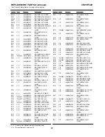
Page 37: ...R C206 C P 600463713004 CAP ELECT 47UF 25V C207 T0000677 6490A3184005 CAP CERAM SMD 22NF 50V X7R C208 C P 601079541003 CAP ELECT 2 2UF 100V C209 T0000632 647984125004 CAP CERAM SMD 100NF 25V X7R C221 T0000632 647984125004 CAP CERAM SMD 100NF 25V X7R C301 T0000641 600763662000 CAP ELECT 10UF 50V C303 C P 601078320003 CAP ELECT 1UF 100V C304 C P 601079541003 CAP ELECT 2 2UF 100V C305 T0000677 6490A3...

Page 38: ... T0000648 648084136006 CAP CERAM SMD 33NF 50V X7R C477 T0000649 6490A3178006 CAP CERAM SMD 5 6NF 50V X7R C477R T0000649 6490A3178006 CAP CERAM SMD 5 6NF 50V X7R C477R T0000649 6490A3178006 CAP CERAM SMD 5 6NF 50V X7R C477R T0000649 6490A3178006 CAP CERAM SMD 5 6NF 50V X7R C478 T0000641 600763662000 CAP ELECT 10UF 50V C479 C P 601079541003 CAP ELECT 2 2UF 100V C480 T0000641 600763662000 CAP ELECT 1...

Page 39: ...D 220PF 50V NPO C830 T0000653 6375A3165002 CAP CERAM SMD 220PF 50V NPO C901 T0000668 610160960000 CAP POLYPROPYLENE 220NF 250VAC C902 T0000666 644263745003 CAP CERAM 4 70NF Z5U 900VAC C903 T0000666 644263745003 CAP CERAM 4 70NF Z5U 900VAC C904 T0000670 642863827000 CAP CERAM 4 7NF 500V Y5U C905 T0000800 605095320008 CAP ELECT 330UF 400V C906 T0000762 650463866005 CAP POLYESTER 33NF 250V C907 T0000...

Page 40: ...T CABLE 3V 300V 24 500MM FC803 T0000694 7303A3489005 CONECTOR HOLDER 2 54MM FC806 N A 4102A4942015 FLAT CABLE 6V 300V 24 600MM FC806 T0000695 7306A4943003 CONECTOR HOLDER GND2 T0000810 4103A1227016 CABLE ASSEMBLY 1V 150MM IC101 T0000811 461598900005 IC M37274MA MICRO M37274EFSP IC102 T0000812 461252142000 IC M24C04 EEPROM 4K X24C04P IC103 T0000813 461494724008 IC PST9131 T RESET IC401 T0000814 461...

Page 41: ...TA144EKA Q922 T0000722 462062240005 TRANSISTOR 45V 500MA NPN 160 320 Q923 T0000727 462162287001 TRANSISTOR 250V 50MA PNP R101 N A 6666A5317000 RES SMD 4 7K 5 63MW R102 N A 6666A5318006 RES SMD 5 6K 5 63MW R103 T0000830 6666A5345000 RES SMD 2 2M 5 63MW R104 N A 6666A5300000 RES SMD 220R 5 63MW R105 N A 6666A5326008 RES SMD 22K 5 63MW R106 N A 6666A5326008 RES SMD 22K 5 63MW R107 T0000831 6666A53420...

Page 42: ...330MW R393 C P 660400487007 RES CARB 1K 5 330MW R393R C P 660400487007 RES CARB 1K 5 330MW R401 N A 6666A5293008 RES SMD 75R 5 63MW R402 N A 6666A5321006 RES SMD 8 2K 5 63MW R411 N A 6666A5328000 RES SMD 33K 5 63MW R413 N A 6666A5307005 RES SMD 680R 5 63MW R413R N A 6666A5307005 RES SMD 680R 5 63MW R414 T0000834 666464144003 RES CARBON METAL 8 2R 5 0 5W R414R T0000834 666464144003 RES CARBON METAL...

Page 43: ...3904004 RES METAL 100K 5 0 5W R713 C P 6666A5313004 RES SMD 2 2K 5 63MW R714 C P 660400502006 RES CARBON 18K 5 330MW R715 C P 660464133001 RES CARBON 8 2K 5 330MW R717 C P 660400487007 RES CARB 1K 5 330MW R720 C P 660400480002 RES CARBON 270R 5 330MW R721 N A 6666A5322002 RES SMD 10K 5 63MW R722 T0000838 662899384000 RES METAL 10R 5 2W R723 C P 660400475009 RES CARBON 100R 5 330MW R724 C P 6604004...

Page 44: ...07 RES METAL 120K 1 400MW R942 N A 6667A5357008 RES SMD 2 7K 1 63MW R943 N A 6666A5334000 RES SMD 82K 5 63MW R944 N A 6666A5338005 RES SMD 220K 5 63MW R945 C P 660400487007 RES CARB 1K 5 330MW R946 N A 6666A5308001 RES SMD 820R 5 63MW R950 C P 662763911000 RES METAL 10M 5 0 5W RL901 T0000848 430294715009 RELAY FOR DEGAUSS COIL S101 T0000849 430197243000 TACT SWITCH S102 T0000850 430197240001 TACT ...

Page 45: ...T SINK KTC802 30 Q704B N A 212160746009 WASHER PR 3 2X5 5X0 8 Q704C N A 210160708000 SCREW M3X12 PAN Q704D N A 211160753005 NUT M3 CR Q901A N A 5602A5212013 HEAT SINK REG PWR SOURCE Q901B N A 212160746009 WASHER PR 3 2X5 5X0 8 Q901C N A 210160708000 SCREW M3X12 PAN Q901D N A 211160753005 NUT M3 CR RING01 N A 5701A9155011 SPEAKER RING SCRW01 C P 2103A9339005 SCREW PP3 20X16 PAN SCRW02 C P 210360737...

Page 46: ......

Page 47: ......

Page 48: ......

Page 49: ......

Page 50: ......

Page 51: ......

Page 52: ......

Page 53: ......

Page 54: ......

Reviews: