background image

54

Acappella  —  Instruction Manual

Section 4 — Software and Configuration


4.

Click 

Apply Changes

. The device resets, and the new IP address will be 

reported in the left pane of NetConfig screen. 

Figure 17.  New IP Address

When all devices have unique IP addresses, it can be extremely helpful to 
label each device with its currently assigned IP address. Sticky labels that 
can be removed are advisable, since the IP address may be changed in the 
future. To identify a specific remote panel when several are connected at 
once, send a reset command to a panel and see which front panel buttons 
go off and back on.

Load Software

Use NetConfig to load software to Acappella routers and Acappella 
Remote Panels.

1.

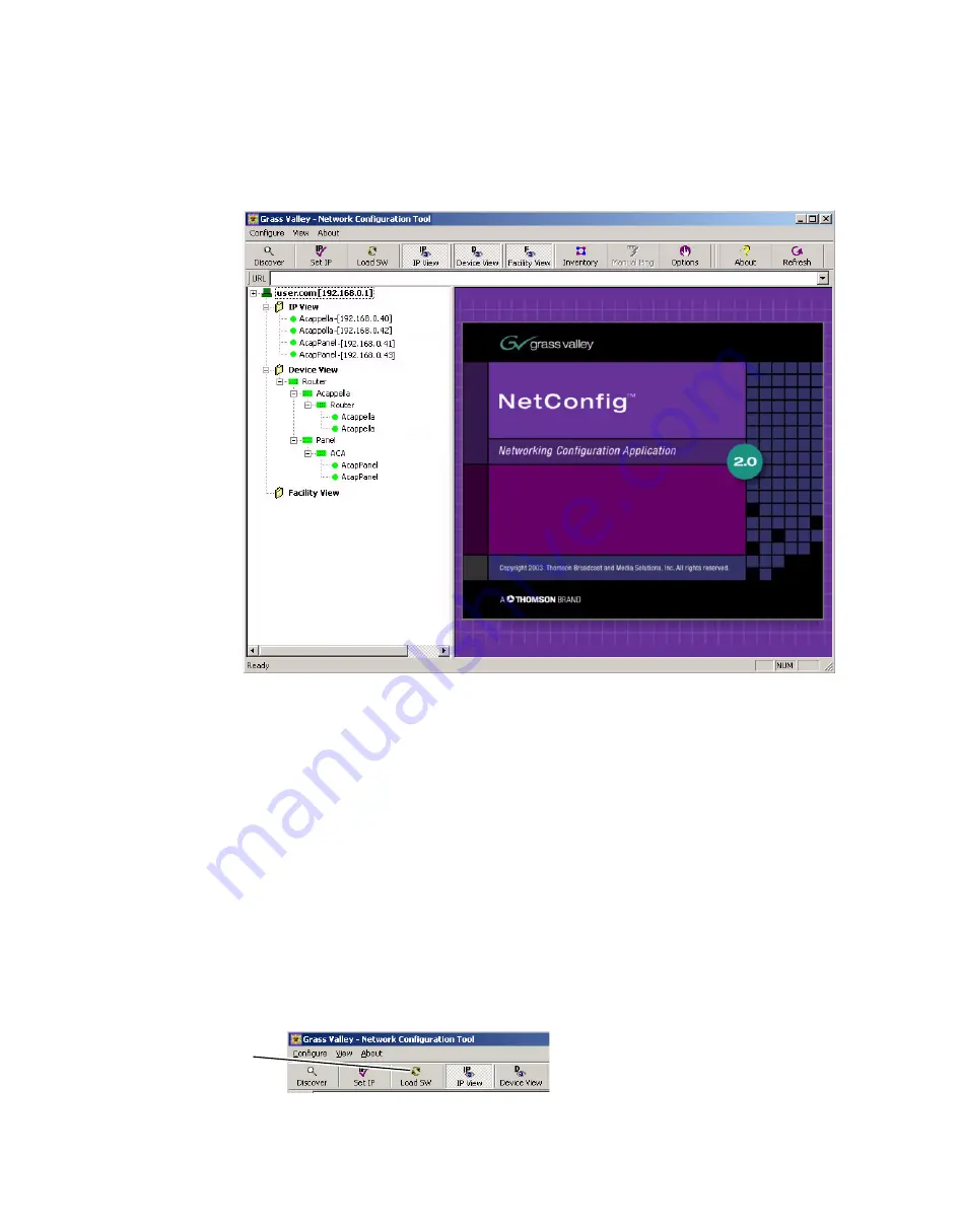
Open NetConfig and select the 

Load SW

 button in the toolbar.

Figure 18.  Load SW

Load SW button

Summary of Contents for Grass Valley Acappella

Page 1: ...Acappella ROUTING SYSTEM Instruction Manual SOFTWARE VERSION 3 1 0 071830006 NOVEMBER 2008...

Page 2: ...Blvd Salt Lake City UT 84119 United States 7140 Baymeadows Way Suite 101 Jacksonville FL 32256 United States Including its implementation meets the requirements of the standard ISO 9001 2000 Scope The...

Page 3: ...Acappella ROUTING SYSTEM Instruction Manual SOFTWARE VERSION 3 1 0 071830006 NOVEMBER 2008...

Page 4: ...aine Uzbekistan 7 095 2580924 225 Switzerland 41 1 487 80 02 S Europe Italy Roma 39 06 87 20 35 28 Milan 39 02 48 41 46 58 S Europe Spain 34 91 512 03 50 Benelux Belgium 32 0 2 334 90 30 Benelux Nethe...

Page 5: ...ation 16 Section 1 System Overview 17 Introduction 17 Features 17 Hardware Description 18 Front Panels 18 Backplanes 21 Video Configuration Digital and Analog 21 Digital Audio Configuration 23 Analog...

Page 6: ...onfig Manual 52 Setting IP Addresses 52 Load Software 54 Web Browser Interface 56 Acappella Configuration Pages 57 Router Configuration 57 Router Status Page 57 Router System Configuration Page 58 Rou...

Page 7: ...etCentral SNMP Manager 91 Third Party SNMP Managers 91 Acappella SNMP Agent Licensing 91 Monitored Acappella Matrix Parameters 93 Acappella Matrix Traps 94 Source and Destination Signal Loss Configura...

Page 8: ...8 Acappella Instruction Manual Contents...

Page 9: ...Acappella Instruction Manual 9 Preface About This Manual This manual provides installation configuration operation safety and regulatory information for the Acappella small router products...

Page 10: ...10 Acappella Instruction Manual Preface...

Page 11: ...o so Safety Terms and Symbols Terms in this Manual Safety related statements may appear in this manual in the following form WARNING Warning statements identify conditions or practices that may result...

Page 12: ...rotective grounding terminal which may be connected to earth ground as a supplement to an internal grounding terminal Indicates that static sensitive components are present which may be damaged by ele...

Page 13: ...onnect both power supply cords prior to servicing Double pole neutral fusing Disconnect mains power prior to servicing Use proper lift points Do not use door latches to lift or move equipment Avoid me...

Page 14: ...Power cords for this equipment if provided meet all North American electrical codes Operation of this equipment at voltages exceeding 130 VAC requires power supply cords which comply with NEMA configu...

Page 15: ...own expense Changes or modifications not expressly approved by Grass Valley can affect emission compliance and could void the user s authority to operate this equipment This device complies with Part...

Page 16: ...Certification This product s components have been evaluated and meet the Safety Cer tification Standards listed in Table 1 Table 1 Safety Certification Standards Component Standard Designed Tested fo...

Page 17: ...gang chop panel enable and destination pro tect An Acappella router comes ready to operate right out of the box just plug it in and you can get right to work It also supports Web browser based con fig...

Page 18: ...ith Grass Valley Prelude and Encore systems Hardware Description Front Panels The front of the Acappella frame and the related remote panels will vary with the configuration of the system All Acappell...

Page 19: ...n the frame s con figuration for local panels and the desired configuration for remote panels Figure 2 is a panel with 16 Sources and 16 Destinations Figure 2 16x16 Front 8300_00_08r0 Figure 3 is a pa...

Page 20: ...nation Front Remote Panel Only 8300_00_12r0 Figure 7 is a panel with 8 Sources and 8 Destinations Figure 7 8x8 Front 8300_00_13r0 Figure 8 is a panel with 8 Sources and 4 Destinations Figure 8 8x4 Fro...

Page 21: ...white areas and are located in the top and bottom rows of the white areas Figure 10 Acappella Backplane 8300_00_34 Video Audio Control Video Configuration Digital and Analog The video BNC backplanes a...

Page 22: ...Backplane 8300_00_25 1 16 15 2 14 13 12 11 3 10 9 4 16 15 5 14 13 6 12 11 7 8 7 8 6 5 9 4 3 10 2 1 V I D E O The configuration shown in Figure 15 is 8 Inputs by 8 Outputs Figure 15 8x8 Video BNC Back...

Page 23: ...Backplane 8300 00 35 Digital Audio Configuration The configuration shown in Figure 18 is 16 Inputs by 16 Outputs of single stream digital AES audio Figure 18 16x16 Audio Single Stream BNC Backplane 83...

Page 24: ...20 16x4 Audio Single Stream BNC Backplane 8300_00_28 The configuration shown in Figure 21 is 16 Inputs by 2 Outputs of single stream digital AES audio Figure 21 16x2 Audio Single Stream BNC Backplane...

Page 25: ...shown in Figure 23 is 8 Inputs by 4 Outputs of dual stream digital AES audio Figure 23 8x4 Audio Dual Stream BNC Backplane 8300_00_33 The empty configuration shown in Figure 24 is used on systems tha...

Page 26: ...The bottom row of analog audio connectors are mounted upside down in relation to the top two rows due to internal board space limitations The removable connectors are wired the same regardless of row...

Page 27: ...f the Acappella router identifies the configuration of the frame Table 2 Acappella Routers Example Model Code A 16 8 HR DU L P Chassis Options L Local control panel P Internal redundant power supply d...

Page 28: ...e Control panels are also available in many different con figurations Table 3 Table 3 Acappella Remote Control Panels Example Model Code A 16 1 RCP GPI GPI Joystick Override Indicates Remote Control P...

Page 29: ...nch rack The frame occupies 1 rack unit Cooling is by horizontal front to back airflow See Figure 29 Figure 29 Acappella Installation Front View 8103_00_37 44 mm 1 75 in 432 mm 17 in 392 mm 15 43 in 4...

Page 30: ...special tools or adaptors Simply position the Remote Panel in the rack and secure the panel in place Refer to Figure 30 Figure 30 Rack Mount Remote Panel Installation 8300_00_48r0 Measurements do not...

Page 31: ...31 16x16 Cabling 8300_00_04 Video Outputs 1 3 5 7 Video Outputs 9 11 13 15 Video Inputs 11 13 15 Video Outputs 2 4 6 8 Video Outputs 10 12 14 16 Video Inputs 12 14 16 Audio Outputs 1 3 5 7 Audio Outpu...

Page 32: ...ply is optional Figure 32 8x8 Cabling 8300_00_05 Video Outputs 1 3 5 7 Video Outputs 2 4 6 8 Audio Outputs 1 1 1 3 1 5 1 7 Audio Outputs 2 1 2 3 2 5 2 7 Audio Outputs 1 2 1 4 1 6 1 8 Audio Outputs 2 2...

Page 33: ...row of connectors be oriented upside down but the removable connectors are wired the same regardless of row used Figure 33 Analog Audio Backplane 8300_02_54_r0 Figure 34 Phoenix Connector Pinouts for...

Page 34: ...l RS 422 9 Pin D connector Table 5 Serial D Connector Pinouts Controlled Pin Function Pin Function 5 6 9 1 9 Pin D Female 1 GND 6 TX Com 2 TX 7 TX 3 RX 8 RX 4 RX Com 9 GND 5 NC Note Refer to the lates...

Page 35: ...own in Figure 36 is the default cabling for plug and play Figure 36 Video Reference Connections 8300_00_50 75 ohm Terminator Reference Generator See Router Reference Configuration Page on page 73 to s...

Page 36: ...e Figure 39 Figure 39 Remote Panel Cabling 8300_00_07r1 LAN AC Power Power Digital Frames The Acappella digital frame uses internal auto ranging AC power supplies One Power Supply is standard the opti...

Page 37: ...P J2 J1 SERIAL PWR PWR PWR PWR 8300_02_59r0 Female Plug Female Plug Male Plug Male Plug Power Supply Redundant Power Supply Defaults for Plug and Play Default Levels are determined by the router s phy...

Page 38: ...38 Acappella Instruction Manual Section 2 Installation...

Page 39: ...ere is power to the panel See Figure 1 Button illumination will be either Off Backlit Low Tally or High Tally depending on the button s status Figure 1 16x8 Local Panel Layout 8300_00_52r0 1 1 2 2 3 3...

Page 40: ...o the current Source on a protected Destination either by action on this panel or by any remote device via ethernet action Any device can enable or disable the Destination protection The Protect butto...

Page 41: ...tination If Destination Gang and All Levels are active Local Panel Press and release of a Source button connects that Source to all Destina tions in the Gang All Destination buttons in the Gang are Hi...

Page 42: ...ation Button Single Destination Button Action Single Destination button press and release causes the following actions Activates that Destination Inactivates all other Destinations Active Destination...

Page 43: ...ally Level Button The left most enabled Level button is the Tally Level it is High Tally and the Source Tally is updated to be the Source on this Level Single Level Button Action Press and release of...

Page 44: ...A VSA Audio Source A ASA DVTR 1 Acappella Video Audio VSB ASB ASB 8300_00_45 ASA ASA ASA VSA VSA VSA A Breakaway Take is performed by accessing the control Levels of a Desti nation individually and s...

Page 45: ...l use must be configured to operate on the Acappella stand alone network This is accomplished by setting the IP address of the PC to be compatible with the IP addresses of the Acappella system compone...

Page 46: ...remote panels these defaults will need to be changed See Setting IP Addresses on page 52 for specific instructions Software Acappella ships with a software CD Several applications on the CD enable you...

Page 47: ...Acappella Instruction Manual 47 Software 2 Click Next when the Welcome screen appears Figure 4 Welcome Window 3 Select I Agree then click Next Figure 5 License Windows...

Page 48: ...4 Click Next to accept the default directory or Browse to select a different location for the directory Figure 6 Directory Window 5 Click Next to accept all the applications or deselect any applicati...

Page 49: ...anual 49 Software 6 Click Yes to backup current files This only applies to upgrading or reinstalling the software Figure 8 Start Installation Window 7 Click Next to begin the Installation Figure 9 Sta...

Page 50: ...1 Finish Window NetConfig The NetConfig application is designed to make network configuration simple NetConfig discovers devices on the network and these devices can be configured remotely using the P...

Page 51: ...d the IP address of the PC on which NetConfig is running The current status of each discovered device is reported by the color of its icon A red dot for example indicates a device is no longer communi...

Page 52: ...esses see Default System IP Addresses on page 46 Resolving duplicate IP addresses is easily accomplished with NetConfig If a device is installed on the network with the same IP address as another devi...

Page 53: ...ght one of the devices with a duplicate IP address Figure 15 Duplicate IP 3 Click Edit then change the last octet of at device s IP address to be unique The first three octets of all the IP addresses...

Page 54: ...ch device with its currently assigned IP address Sticky labels that can be removed are advisable since the IP address may be changed in the future To identify a specific remote panel when several are...

Page 55: ...Matrices will appear in the right pane of the window see Figure 20 Figure 20 Acappella Matrix 4 Check the box for the Acappella to update in the Client Name list 5 Check the Re Boot when complete che...

Page 56: ...l s re boot when the software update is complete 11 Click the Load button to begin the update 12 Once all Panel downloads are complete use the Refresh button to update the window and check that the ve...

Page 57: ...e information dis played here is entered automatically such as Product Part Number Serial Number etc The Location and Asset Tag can be changed on a different page The Level Source SRC and Destination...

Page 58: ...pages The name will also appear in the NetConfig logical tree list under IP View and Device View The field will accept up to 60 characters However it is recommended that entries be kept short to keep...

Page 59: ...e Parity Data Bits and Stop Bits These settings are used for serial interface settings for the 9 pin D connector on the router These settings are configured according to the requirements of the contro...

Page 60: ...the device can be set directly from its web page by entering the new numbers in the Ethernet IP Subnet Mask and Gateway IP fields You will need to check Do reset and Save New Settings before the chang...

Page 61: ...m must use the same System Identifier port number Alternatively you can assign a specific port number to a device by choosing Manual Select which opens a text entry field This feature is intended only...

Page 62: ...analog video On Digital Video systems the Router Video Configuration Page will not appear unless the Acappella router has a video level The default setting is Auto Auto reclocking will lock to a signa...

Page 63: ...Analog Audio Acappella systems do not display an AES Configuration Page Figure 26 Router AES Output Configuration Page Several digital audio attributes may be assigned The defaults are Resolu tion 20...

Page 64: ...B to Channel A A Only Channel A to Channel A and to Channel B and B Only Channel B to Channel A and to Channel B Only one of the four variations can be active Invert When a channel is inverted a minu...

Page 65: ...Left Right Left Right 8053_00_09_r0 Table 3 AES Attributes AES Attribute Description AES Attribute Description Invert Left Inverts Left Channel 1 only Right Channel 2 is not affected Invert Left Right...

Page 66: ...nverts Left Channel 1 and Right Channel 2 then Right Channel 2 is sent to both Channel 1 and Channel 2 Invert Left Right Sum Inverts Left Channel 1 and Right Channel 2 then Left Channel 1 and Right Ch...

Page 67: ...ple screens in Figure 31 and Figure 32 show two frames creating a four Level system Figure 31 shows a frame that has a single Wideband HD reclocking 8x8 Level By combining this frame with another fram...

Page 68: ...l 1 on all frames in the system You can create systems with up to 4 Levels To change the order of the Levels use the Move column radio buttons Figure 32 Three Level Local Frame with One Remote Level C...

Page 69: ...Manual 69 Acappella Configuration Pages 2 Verify IP Addresses and Type are correct for remote Levels select Save New Matrix Config and Reset Router Figure 33 First Frame Level 1 3 Select second frame...

Page 70: ...roper place as Level 2 Note To move Levels always use the Up and Down buttons never try to reorder Levels using IP Addresses Figure 34 Second Frame Level 2 Move Down Figure 35 Second Frame Level 2 5 V...

Page 71: ...e enable 3 remote Levels Figure 36 Third Frame Level 3 7 Use Down to move the Level to it proper place as Level 3 Figure 37 Third Frame Level 3 Move Down 8 Verify IP Addresses and Type are correct for...

Page 72: ...tware and Configuration Figure 38 Third Frame Level 3 After Move Down 9 Select the fourth frame enable three remote levels on the Remote Configuration page order the levels to match the other three fr...

Page 73: ...tment relates to the total range There are two indica tors one for Vertical Offset and one for Horizontal Offset With Offsets set to zero 0 switches occur with respect to reference input The default s...

Page 74: ...ne Acappella frame one frame will show State Server and the rest of the frames will show a State Client Figure 40 Server and Client States In a system with only one frame and no remote panel the State...

Page 75: ...n Pages Router Factory Defaults Page Router Factory Defaults page shows the settings for the items that have factory defaults To restore the listed settings to the factory defaults click on the Restor...

Page 76: ...n 4 Software and Configuration Acap Router Applications Page The Acap Router Applications page shows the Device ID of the matrix and permits entering License Key information for the SNMP option Figure...

Page 77: ...truction Manual 77 Acappella Configuration Pages Maintenance Page The System Maintenance pages are intended only for use by factory engi neers for testing and troubleshooting Figure 43 Figure 43 Maint...

Page 78: ...on Remote Panel Configuration Panel Description Page Panel Description page is a read only page All of the information dis played here is entered automatically except the Panel Device Name which is en...

Page 79: ...ame will also appear in the NetConfig logical tree list The field will accept up to 60 characters However it is rec ommended that entries be kept short to keep the name from wrapping Asset Tag This fi...

Page 80: ...ttons can be seen in a dark environment Panel Dim Button Intensity This setting is used to adjust the button brightness at Low Tally Panel Display Intensity This setting is not used Panel Console Baud...

Page 81: ...re than one panel or frame in a system duplicate IP addresses may exist To resolve duplicate IP Addresses see Setting IP Addresses on page 52 The IP addresses of the device can be set directly from it...

Page 82: ...the same System Identifier port number System Broadcast Select Leave this setting at Use Broadcast if your Acappella system has none or only a small number of remote panels three or less Selecting Use...

Page 83: ...ruction Manual 83 Acappella Configuration Pages Remote Panel Factory Defaults Panel Factory Defaults page displays the factory default settings This is a read only page Figure 47 Remote Panel Factory...

Page 84: ...ration Remote Panel Acappella Destination Configuration Destination Configuration page is used to assign physical connector to specified Destination button A reset is required for reassignments to tak...

Page 85: ...Table 5 and enter the IP Address of the router Table 5 Level Types Acappella HD R HD Wideband Digital Video Reclocking Acappella SD R SD Digital Video Reclocking Acappella SD B SD Digital Video Non r...

Page 86: ...at employs synchronous serial ASCII commands Commands may be issued to control the router by either an operator entering commands manually using a terminal interface like hyperter minal or by an autom...

Page 87: ...ypes However each Acappella frame can be configured with only one video level and one audio level Multiple video or audio levels up to four each require multiple Acappella frames Control Panels Acappe...

Page 88: ...88 Acappella Instruction Manual Section 4 Software and Configuration...

Page 89: ...shooting Check Connections Connections should be tight and electrically sound Cables should be checked for damage Check Inputs AC power connections Signal input video audio must be present and within...

Page 90: ...figuration web page SNMP Monitoring Acappella supports the Simple Network Management Protocol SNMP for system monitoring SNMP Agents reside on the monitored equipment and SNMP monitoring software resi...

Page 91: ...rix MIB GVG Acappella MIB GVG Element MIB Third Party SNMP Managers Other industry standard Third Party SNMP Managers can monitor Acap pella matrices For their installation configuration please contac...

Page 92: ...nd Troubleshooting The Acappella Device ID is displayed on the Acap Router Application web page Clicking on the Enter License Key button opens a window allowing entry of the license key Figure 51 Figu...

Page 93: ...Asset tag of Acappella matrix This can be configured from SNMP Manager as well as Web page This is stored as persis tent data so is retained across reboots Network Information IP Address Subnet Mask...

Page 94: ...nd traps on changes in the Output signal status unless it is configured to do so This trap needs to be enabled using Acappella Matrix Web Page screen Loss of Control Point If Acappella matrix detects...

Page 95: ...For example if the matrix is digital video only there will be no AES configura tion web page Video Destination and Source SNMP configuration is accessed via the Video Config web page Figure 52 and Fi...

Page 96: ...96 Acappella Instruction Manual 5 Maintenance and Troubleshooting Figure 53 Video Source SNMP Configuration...

Page 97: ...Acappella Instruction Manual 97 SNMP Monitoring Figure 54 AES Source SNMP Configuration...

Page 98: ...98 Acappella Instruction Manual 5 Maintenance and Troubleshooting Figure 55 AES Destination SNMP Configuration...

Page 99: ...10 90 non condensing Video Specifications Video Reference Table 9 Video Reference Specifications Video Format NTSC 525 Line Standard switching middle of line 10 PAL 625 Line Standard switching middle...

Page 100: ...reclocking S Non reclocked operation or bypass switched from 10 Mbps to 540 Mbps with signals that have a maximum ones zeros ratio of 20 1 DVB ASI Supported Polarity is preserved Wideband Digital Vide...

Page 101: ...m source terminated Return Loss 40dB DC to 10MHz Nominal Level 1Vpp max 2Vpp into 75 ohm termination Coupling DC DC Offset 50mV Equalization None Analog Video Performance Frequency Response 0 1dB DC t...

Page 102: ...Impedance 75 ohm Return loss 25dB 0 1 6mhz 75 ohms unbalanced Sample rate 48KHz AES Outputs Format SMPTE 276 M specifies AES3 Connector BNC Impedance 75 ohm Voltage 1 Vpp into 75 ohms Rise time Approx...

Page 103: ...ed 24dBu Balanced into 600 Feet Belden 8451 cable 600 Ohms Capacitance of cable equivalent to 0 022uF Output Impedance 25 Ohms Differential OCMR Output Common Mode Rejection 46dB DC on Output Differen...

Page 104: ...104 Acappella Instruction Manual Appendix A Specifications...

Page 105: ...status QI Qi Query Destination Status on a Specific Level by Index QJ Qj Query Destination Status by Index QN Query Names IS Source names with Source indices ID Destination names with Destination ind...

Page 106: ...lla Instruction Manual Appendix B Native Protocol Note Commands like QN IS and QN ID will receive dummy source destination names such as dst_1 dst_2 from Acappella The Acappella NP server uses Control...

Page 107: ...79 router 58 Audio Analog dual stereo 26 Audio Backplane Analog 16x16 26 16x4 26 Audio Backplane BNC 16x16 23 16x2 24 16x4 24 16x8 23 8x4 25 8x8 24 Empty 25 Audio Backplane Dual Analog 8x4 27 8x8 27...

Page 108: ...Ethernet cabling 34 F factory defaults 75 83 FAQ database 4 features 17 Frame model codes 27 frequently asked questions 4 Front 16x1 20 16x16 19 16x2 19 16x4 19 16x8 19 8x1 20 8x4 20 8x8 20 No Local P...

Page 109: ...uts analog audio 33 Serial D connector 34 Prelude control of Acappella 17 problem reference 90 R rack mounting rear frame support 30 rear frame support kit 30 reference adjustments 73 problem 90 video...

Page 110: ...Identifier 60 82 T Take All Level 44 All Level Illustration 44 Breakaway Illustration 44 Terminal Computer Interface T CI protocol 86 V Video settings 62 Video Backplane 16x16 21 16x2 22 16x4 22 16x8...

Reviews: