9
•
Activate the adjustment mode display (SBL item). Ajust
SBL
from
0
to
1.
Blanking the bottom of
the screen.
•
Adjust
VSH
until the bottom of the pattern be aligned with the reference marks of the mechanical
center on picture tube (the central vertical line in the center of the tube).
•
Adjust
VS
until the central line be aligned with the half bottom of the screen (the central line of the
circle pattern in the half cut of the screen)
•
Return
SBL
from
1
to
0
value . The image could be compressed or expanded.
•
Select
VA
item and set its value to adjust the size of the picture (proportional height and width
picture).
•
If necessary readjust
SC
item and set its value to adjust the Linearity (acts in the top of the image)
and
VA.
NOTE: The
SC
and
VA
adjustments are interdependent (they should be used together).
When the image to be decentralized in the vertical, to retouch
VSH
and/or
VS
3.7 Horizontal Adjustment
•
Apply a Circle Pattern Philips (RF Input)
•
Using the remote control, set the MAGIC mode “ORIGINAL”
•
Activate the adjustment mode display (HSH item). Select
HSH
item and set its value to adjust the
horizontal symmetry of the pattern;
•
Select
HP
and
HB
items and adjust its value if necessary.
3.8 MAGIC Adjustment
•
Adjustment of original magic should have been according to pattern
•
Receive the color bar pattern (
NTSC signal, RF input)
•
Connect the oscilloscope probe to the collector of Q830 (cathode G)
•
Using the remote control, set the image controls as follow:
Brightness:
adjust to central position (8 Bars)
Contrast:
adjust from maximum to minimum (4 Bars)
Color: adjust from minimum to maximum (5 Bars)
Sharpness:
adjust from minimum to maximum (3 Bars)
Tint:
adjust to the center (8 Bars)
•
After the image menu preset, turn off the television and activate the service menu. Select
ORIGMAG
item;
Summary of Contents for CR14300
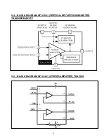
Page 11: ...13 5 2 BLOCK DIAGRAM OF IC 101 TDA9380 ...
Page 12: ...14 5 3 BLOCK DIAGRAM OF IC 490 BU4052 ...
Page 14: ...16 5 6 BLOCK DIAGRAM OF IC 450 STEREO DECODER ...
Page 15: ...17 5 7 BLOCK DIAGRAM OF IC 430 LMC568 PLL SAP ____________________________________________ ...
Page 64: ......
Page 65: ......


