27
″ LCD TV Thomson 27LM051B6
35
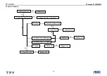
Fig.7
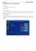
1.OFFSET(26%) W/B ADJUSTMENT(This is only for AV/TV)
:
Change the input signal to 26% white level
performance .Set the CHROMA7120 to 288 301 30 and MODE_RGB ,then adjust the TV
’s RB
、
GB
、
BB to make
CHROMA7120 display to 100.
2.W/B ADJUSTMENT (100%): Change the input signal to 100% white level performance. Set the
CHROMA7120 to 288 301 415 and MODE_RGB , then adjust the TV
’s RG
、
GG
、
BG to make CHROMA7120 display
to 100.
3.Save the adjustment. Then change the input signal to 26% white level performance. Set the CHROMA7120 to
MODE_RGB and CH3, check whether the color temperature was in SPEC (color spec is x
±
15;y
±
15;Y
±
15). In this
time, most of the TV is in SPEC, while the others should be adjusted twice or more to make its color temperature in
SPEC.
4.CHECK CUT OFF: Change the input signal to 0% white level performance. Firstly, press the
“brightness” from
50% to 0% and make sure the Y is not changed. Secondly, change the input signal to 32 GRAYS performance and
make sure the grays is not connected at any position.( as the 5% level is between the first gray and the second gray.
5%=
(
1/32
)
*1.6
。
)
1.The white color temperature in PC Mode should be app.7200K(CIE1931: x=0.303, y=0.319
,
Y>350),
10300K(CIE1931 : x= 0.278, y= 0.289, Y>350 ).
2.The white color temperature in AV/TV Mode should be app. 8700K(CIE1931:x=0.288±15, Y=0.301±15,
Y>370). In this Mode,we should check the black balance,which level is 26% of the white level(1.0Vpp).
3. The white color temperature in HDTV/HDMI Mode should be app. 8700K(CIE1931:x=0.288±15, Y=0.301±15,
Y>370)
Those three channels should be factory preset and not be possible to be modified.
The measurement position is the center of the display(5) at brightness set to center and
Contrast set to max. . The tolerance of the color coordinates should be less than ± 0.015
Summary of Contents for 27LM051B6
Page 4: ...27 LCD TV Thomson 27LM051B6 4 2 Operations Instructions 2 1 The Use Of Remote Control ...
Page 5: ...27 LCD TV Thomson 27LM051B6 5 2 2 The Use Of Teletext ...
Page 6: ...27 LCD TV Thomson 27LM051B6 6 2 3 Front Panel Control Knobs ...
Page 7: ...27 LCD TV Thomson 27LM051B6 7 2 4 OSD Operations ...
Page 8: ...27 LCD TV Thomson 27LM051B6 8 ...
Page 9: ...27 LCD TV Thomson 27LM051B6 9 ...
Page 10: ...27 LCD TV Thomson 27LM051B6 10 ...
Page 11: ...27 LCD TV Thomson 27LM051B6 11 ...
Page 12: ...27 LCD TV Thomson 27LM051B6 12 ...
Page 13: ...27 LCD TV Thomson 27LM051B6 13 ...
Page 14: ...27 LCD TV Thomson 27LM051B6 14 ...
Page 15: ...27 LCD TV Thomson 27LM051B6 15 2 5 How To Connect ...
Page 16: ...27 LCD TV Thomson 27LM051B6 16 ...
Page 17: ...27 LCD TV Thomson 27LM051B6 17 ...
Page 18: ...27 LCD TV Thomson 27LM051B6 18 ...
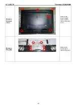
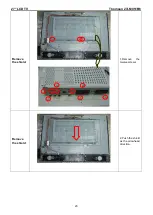
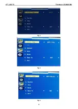
Page 34: ...27 LCD TV Thomson 27LM051B6 34 Fig 4 Fig 5 Fig 6 ...
Page 98: ...27 LCD TV Thomson 27LM051B6 98 8 PCB Layout 8 1 Main Board 715T1616 1 ...
Page 99: ...27 LCD TV Thomson 27LM051B6 99 ...
Page 100: ...27 LCD TV Thomson 27LM051B6 100 8 2 Power Board 715T1180 3 ...
Page 101: ...27 LCD TV Thomson 27LM051B6 101 ...
Page 102: ...27 LCD TV Thomson 27LM051B6 102 ...
Page 103: ...27 LCD TV Thomson 27LM051B6 103 8 3 Tuner Board 715T2170 1 ...
Page 105: ...27 LCD TV Thomson 27LM051B6 105 8 7 Headphone Board 715T1290 1 5 ...
Page 107: ...27 LCD TV Thomson 27LM051B6 107 9 2 Power Board ...
Page 108: ...27 LCD TV Thomson 27LM051B6 108 9 3 Exploded View ...
Page 109: ...27 LCD TV Thomson 27LM051B6 109 ...
Page 122: ...27 LCD TV Thomson 27LM051B6 122 10 2 Power Board 715T1180 3 ...
Page 123: ...27 LCD TV Thomson 27LM051B6 123 ...
Page 124: ...27 LCD TV Thomson 27LM051B6 124 10 3 Tuner Board 715T2170 1 ...
Page 125: ...27 LCD TV Thomson 27LM051B6 125 ...
Page 126: ...27 LCD TV Thomson 27LM051B6 126 ...


