background image

2

STEP 5. 

Insert the hex key into the hole in the right 

side of the compressor housing (See Fig. #2). Loosen 

clamping screw at the base of the connecting rod. 

Slide  the  connecting  rod  off  the  bearing,  lift  it  out 

through the top of the compressor housing.

NOTE:

  It  may  be  necessary  to  insert  a  flat  tip 

screwdriver into the slot in the base of the connecting 

rod, and spread the base slightly, in order to break 

the Loctite

®

 bond and free it from the bearing (See 

Fig. #3).


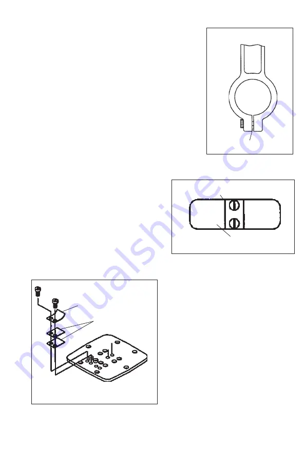
Insert Screwdriver

Figure #3

REBUILD VALVE PLATE 

ASSEMBLY

STEP 1. 

Remove the valve keeper and  

intake  valve  flapper  from  the  bottom  of 

the valve plate. Clean the bottom of the 

plate  with  a  clean  soft  cloth.  Install  the 

new intake flapper valve. The valve keeper 

should be placed on top of the flapper so 

that the word “UP” is visible (See Fig. #4). 

Tighten the screws to 12 in-lbs. 

STEP 2.

 Remove the two restraints and 

four  exhaust  flapper  valves  (two  over 

each port) from the top of  the valve plate. 

Clean the top of the plate with a clean 

soft cloth. Install the new flapper valves 

and screws as shown in Fig. #5. Tighten 

the screws to 12 in-lbs.  Set Valve Plate 

Assembly aside.

UP

Figure #4

Valve Flapper

Valve Keeper

Figure 5

Valve Flappers

Valve Restraint

Summary of Contents for SK100772

Page 1: ...ad screwdriver attachment for torque wrench Flat blade screwdriver attachment for torque wrench Torx T 20 attachment for torque wrench Torx T 25 attachment for torque wrench for head screws 5 32 allen...

Page 2: ...plastic front cover assembly 5 and lift off the cover Place cover and capaci tor assembly off to side leaving it connected to the lead wires STEP 3 Remove the head gasket O ring and discard Turn the v...

Page 3: ...E PLATE ASSEMBLY STEP 1 Remove the valve keeper and intake valve flapper from the bottom of the valve plate Clean the bottom of the plate with a clean soft cloth Install the new intake flapper valve T...

Page 4: ...n until it contacts the housing The 4 locator ribs should bear against the inside surface of the sleeve and the sleeve should hold the dust shield in place STEP 1 Clean the old adhesive from connectin...

Page 5: ...ll the new O ring into the bottom of the valve plate assembly seating it firmly into the groove with your finger or blunt object STEP 6 With the sleeve located and firmly seated on the housing replace...

Page 6: ...e in the eccentric This will prevent the eccentric from rotating while tightening the fan screw Caution To avoid property damage or personal injury always try rotating the fan by HAND prior to connect...

Page 7: ...capacitor is vertical with the leads on top Make sure that the wires are clear of the fan Tighten the front cover screws to 18 in lbs Figure 11 STEP 11 Remove the filter cap from the filter assemlby R...

Page 8: ...3524 Washington Avenue Sheboygan Wisconsin 53081 USA 920 457 4831 www gd thomas com 1419 Illinois Avenue...

Reviews: