background image

20

SUPER  CUT

SUPER  CUT

SUPER  CUT

SUPER  CUT

SUPER  CUT

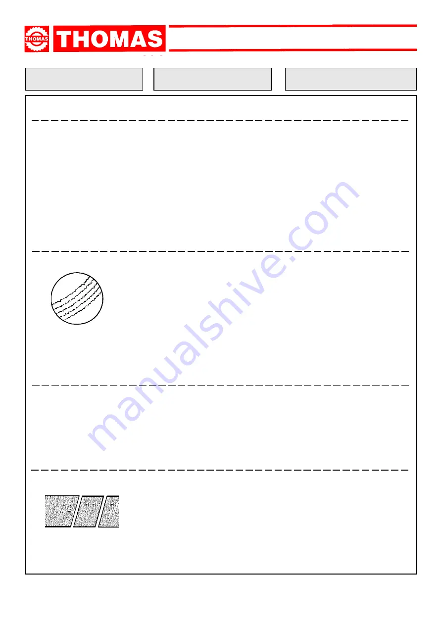
FAULT

PROBABLE CAUSE

REMEDY

Wrong tooth pitch

Unsuitable tooth profile

Ineffective gripping of the part in the
vice.
Dimensions of the solid section too
large with respect to the maximum
admissible cutting dimensions
Disk diameter incorrect and/or too
large

Choose a suitable disk.
See Chapter “Material classification
and choice of disks” .
Choose a suitable disk.
See Chapter

  “Material classification

and choice of disks”

  in the paragraph

on Type of disks.
Check the gripping of the part.

Abide by the instructions.

Decrease the disk diameter, adapting it
to the dimensions of the part to be cut;
the cutting part of the disk must not be
too large for the shape of the part to be
cut.

DISK VIBRATION

CUTS OFF THE STRAIGHT

Decrease advance, exerting less cutting
pressure.
Check the gripping of the part which may
be moving sideways.
Adjust the head.
Choose tool quality carefully in every detail
as regards type and construction cha-
racteristics.
Carefully clean the laying and contact
surfaces.

BLADE STICKS IN THE CUT

Too fast advance

Low cutting speed
Wrong tooth pitch

Sticky accumulation of material on
the disk.
Insufficient lubricating refrigerant

Decrease advance, exerting less cutting
pressure.
Increase speed.
Choose a suitable disk.
See Chapter “Material classification
and choice of disks” .
Check the blend of lubricating coolant and
choose a better quality disk.
Check the level of the liquid in the tank.
Increase the flow of lubricating refrigerant,
checking that the hole and the liquid outlet
pipe are not blocked.

Incorrect emulsion of the lubricating
refrigerant

Check the percentage of water and oil in
the emulsion.

Too fast advance

Ineffective gripping of the part in the
vice
Disk head off the straight
Disk sides differently sharpened.
Disk thinner than the commercial
standard.
Dirt on the gripping device

Disk diameter incorrect and/or too
large

Ineffective gripping of the part in the
vice.
Too fast advance

Disk teeth are worn
Insufficient lubricating refrigerant

Toothing does not unload shavings
well

RIDGES ON THE CUTTING SURFACE

Decrease the disk diameter, adapting it
to the dimensions of the part to be cut;
the cutting part of the disk must not be
too large for the shape of the part to be
cut.
Check the gripping of the part.

Decrease advance, exerting less cutting
pressure.
Sharpen the tool.
Check the level of the liquid in the tank.
Increase the flow of lubricating refrigerant,
checking that the hole and the liquid outlet
pipe are not blocked.
Choose a blade with a larger tooth pitch
that allows better unloading of shavings
and that holds more lubricating refrigerant.

Summary of Contents for 275 SUPER CUT

Page 1: ...THOMAS USE AND MAINTENANCE MANUAL 275 SUPER CUT 300 SUPER CUT 315 SUPER CUT ...

Page 2: ... We are constantly at work searching out a variety of high quality high performance tools to offer at the best prices possible Our commitment to you is that we will not offer cheap junk anywhere on our website You the customer help us to evaluate our products constantly and as soon as an ongoing quality issue is uncovered we will correct it or discontinue that product immediately We hope to earn y...

Page 3: ...R 10 Machine components 13 10 1 List of spare parts 13 CHAPTER 11 Wiring diagrams 17 CHAPTER 12 Troubleshooting 19 12 1 Blade and cutting diagnosis 19 12 2 Electrical components diagnosis 21 CHAPTER 13 Noise tests 21 CHAPTER 14 Optional 22 14 1 Pneumatic vice 22 14 2 Connection to the pneumatic system 22 Plates and labels 22 Notes 23 Contents Contents 2 Ordering spare parts 2 Guarantee 2 Machine c...

Page 4: ...R CUT SUPER CUT Space reserved for the NAME and STAMP of the DEALER and or IMPORTER Machine certification and identification marking MACHINE LABEL SUPER CUT SERIAL NUMBER TYP MODEL YEAR OF MANUFACTURE via Pasubio 32 36033 ISOLA VIC ITALIA ...

Page 5: ...al equipment according to European Standard CENELEC EN 60 204 1 which as similates with some integrating modifications the publication IEC 204 1 The electrical equipment ensures protection against electric shock as a result of direct or indirect contact The active parts of this equipment are housed in a box to which access is limited by screws that can only be removed with a special tool the parts...

Page 6: ...KW 1 5 Max electric absorption KW 1 55 Oil bath reduction unit i 34 1 Max blade diameter mm 275 Min blade diameter mm 250 Blade rotation speed rpm 41 82 Vice opening mm 120 Machine Weight KG 123 Coolant liquid L 5 Working table height with base mm 980 2 speed three phase electric motor KW 1 2 1 6 1 speed single phase electric motor KW 1 5 Max electric absorption KW 1 55 Oil bath reduction unit i 3...

Page 7: ...g with the machine motor characteristics Environment temperature from 10 C to 50 C Relative humidity not over 90 4 3 Anchoring the machine Position the machine on a firm cement floor maintaining at the rear a minimum distance of 800 mm from the wall anchor it to the ground as shown in the diagram using screws and expansion plugs or tie rods sunk in cement ensuring that it is sitting level 2 speed ...

Page 8: ...ng coolant pump and the electrical components 5 5 2 Vice System for gripping material during the cutting operation operated with handwheel and fast manual blocking lever It is provided with an anti burr device for blocking the part that is to be cut Fit the components supplied as indicated in the photo part 1 Screw the lever onto the head and fix it part 2 Fit the bar holding rod part 3 Fix the pe...

Page 9: ...irection indicated if not invert the two phase leads and that sufficient coolant is coming out The cropper is now ready to start work bearing in mind that the CUTTING SPEED and the TYPE of DISC combined with a suitable descent of the head are of decisive importance for cutting quality and for machine performance for further details on this topic see below in the chapter on Material classification ...

Page 10: ...ctionality of the shields and emergency stops 8 2 Weekly maintenance More accurate general cleaning of the machine to remove shavings especially from the lubricant fluid tank Clean the filter of the pump suction head and the suction area Clean and grease the screw and the sliding guide of the vice Clean the disk housing Sharpen the disk teeth 8 3 Monthly maintenance Check tightness of the screws o...

Page 11: ...al graphite cast iron GS600 Malleable cast iron W40 05 212 232 222 96 100 98 245 600 420 9 2 Choosing the disk First of all the pitch of the teeth must be chosen suitable for the material to be cut according to these criteria parts with a thin and or variable section such as profiles pipes and plate need close toothing so that the number of teeth used simultaneously in cutting is from 3 to 6 parts...

Page 12: ... d 1 5 2 2 5 3 3 5 4 4 5 5 6 7 8 h 0 2 mm h 0 3 mm S S S α α α α α γ γ γ γ γ B toothing normal large toothing with or without shaving breaking inci sion BW toothing large toothing with alternate side rake C HZ toothing large toothing with roughing tooth with rake on both sides alternating with a finishing tooth without rake The rou ghing tooth is 0 15 0 30 mm higher 9 7 Type of disks The disks dif...

Page 13: ...per minute Vt m min Cutting speed in metres per minute Az Tooth advance Ng min Number of revs per minute Z Number of teeth on the disk p Tooth depth Heat treated steel R 950 1300 N mm 2 Extra hard steel R 950 1000 N mm 2 Hard steel R 750 950 N mm 2 Semi hard steel R 500 700 N mm 2 Grey cast iron Aluminium and alloys R 200 400 N mm 2 Copper R 200 350 N mm 2 Phosphor bronze R 400 600 N mm 2 Hard bro...

Page 14: ...e pin 68 Hinge pin washer 69 Hinge pin bush 70 Grain M8 71 Nut M8 72 Nut M16 73 Head lever 74 Head lever handgrip 75 GUK ring nut M25x1 5 76 Worm wheel 1 Machine bed 2 Revolving arm 3 Revolving arm locking pin 4 Revolving arm locking bush 5 Revolving arm locking lever 6 Screw M8 7 Countervice 8 Pin 9 Countervice jaws 10 Burr free jaws 11 Countervice fixing pin 12 Roller arm 13 Roller 14 Washer M10...

Page 15: ...ade guard 90 Ring seeger Ø 60E 91 92 93 Tir rod support 94 Washer 95 Screw M8 96 Mobile guard rod 97 Screw M8 98 Washer 99 Bearing 6301 100 GUK ring nut M17x1 101 Worm screw 102 Spacer 103 Spacer Ø 47 104 Bearing 3204 105 Ring DPSM 25 40 7 106 Head gasket 107 Front motor flange 108 Motor shaft rotor 109 Key 110 Washer 111 Stud bolt 112 Nut 113 Motor and stator casing 114 115 116 Rear motor flange ...

Page 16: ...15 SUPER CUT SUPER CUT SUPER CUT SUPER CUT SUPER CUT ...

Page 17: ...NDA 146 Speed switch 147 Reset button 148 Emergency push button 149 Electric components box LEGENDA 140 Auxiliary relay 141 Remore control switch 142 Fuse carrier 143 Transformer 144 Socket connector 145 Plug connector 142 146 147 148 149 140 143 141 144 145 ...

Page 18: ...17 SUPER CUT SUPER CUT SUPER CUT SUPER CUT SUPER CUT 11 WIRING DIAGRAMS V 230 50 Hz CIRCUIT DIAGRAM SINGLE PHASE THOMAS THOMAS ...

Page 19: ...18 SUPER CUT SUPER CUT SUPER CUT SUPER CUT SUPER CUT V 400 50 Hz CIRCUIT DIAGRAM THREE PHASES ...

Page 20: ...ere turning the part Check the level of the liquid in the tank Increase the flow of lubricating refrigerant checking that the hole and the liquid outlet pipe are not blocked Check the blend of lubricating coolant and choose a better quality disk See Chapter Material classification and choice of disks in the paragraph on Running in the disk Change disk speed and or diameter See Chapter Material cla...

Page 21: ...ting less cutting pressure Increase speed Choose a suitable disk See Chapter Material classification and choice of disks Check the blend of lubricating coolant and choose a better quality disk Check the level of the liquid in the tank Increase the flow of lubricating refrigerant checking that the hole and the liquid outlet pipe are not blocked Incorrect emulsion of the lubricating refrigerant Chec...

Page 22: ...ket plug Voltage must arrive upstream from the fuses Check for efficiency Identify and eliminate It must be turned to position 1 or 2 Ensure that it is off and that its contacts are unbroken Check mechanical efficiency Check current continuity on the two wires in the prone after letting the motor cool for about 10 15 minutes If after this time there is no current continuity in the two wires the mo...

Page 23: ...ND LABELS 14 2 Connection to the pneumatic system Connect the tube of the pneumatic system to the filter unit part 1 and check that the pressure gauge part 2 shows a pressure of 6 7 BAR sufficient to ensure optimum functioning of the device The vice opening mechanism is controlled by the valve part 1 operated only if the head is completely lifted Leave a play of 3 4 mm between the jaws and the pie...

Page 24: ..._____ ________________________________________________________________________________ ________________________________________________________________________________ ________________________________________________________________________________ ________________________________________________________________________________ ______________________________________________________________________...

Reviews: