background image

!

!

C.A.S. installation manual 

Page 17

3.9.8 

Programming the GSM/GPS Combimodule


Once the SIM card has been inserted and the holder locked, briefly press the 

“GSM” button (D, Diagram 1) on the printed circuit board of the central unit.


The 4 LEDs now show the state of the module as in Table 2.


If D3 shows the logged-in status, send a ”Programming SMS” 

to the number of the card in the module. Look at the structure 

of a ”Programming SMS” on the diagram below.

Note! Do not use any spaces in the programming SMS. 

The spaces used on the diagram are only there to make it easier 

to understand.

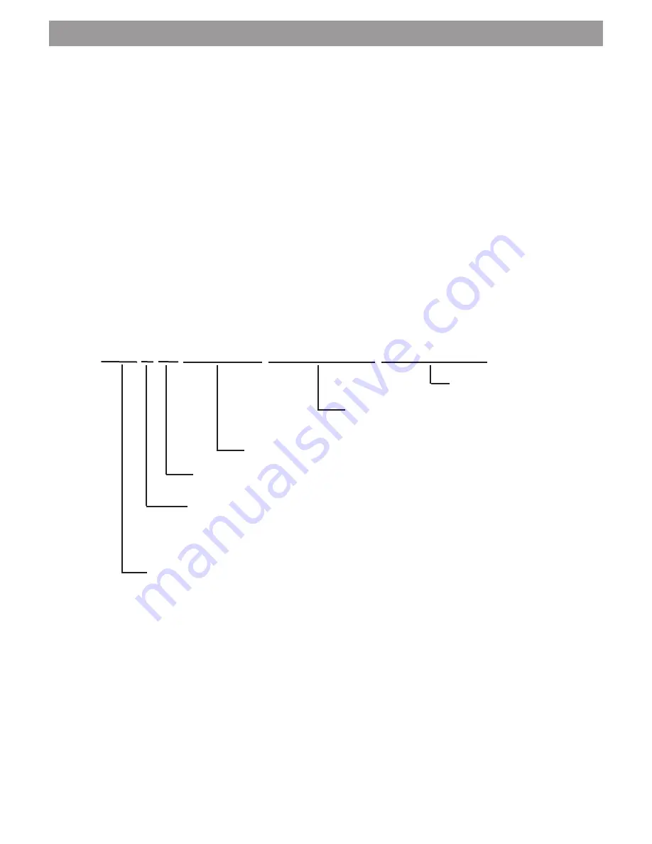
Structure of a programming SMS where all the target phone numbers are 

“Master numbers” (up to 10 target phone numbers are possible):

*100# P +49 1512249 1712349 151 33546798


3rd target phone number


 2nd target phone number including  

country code


Phone number of the mobile phone subscriber


Country code with + in front (+44 for the UK)


 “P” stands for pre-paid card and should be used when one is 

in use. If the P is not transmitted, the remaining credit on the 

card will not be transferred and you will not be informed when 

it is necessary to top up the card.


*100# is used to enquire about the remaining credit on a pre-paid card and 

may consist of other characters (e.g. *101#) depending on the provider. 

The character sequence can be found from the information brochure of  

your pre-paid card.

*100#P is only used for pre-paid cards. With all other cards,  

it cannot be in the programming SMS.

Structure of a programming SMS where not all the target phone numbers are 

“Master numbers” (see 2.1, Page 7):


*100#P+49 15122436169 

- 49 17123456789 - 49 151 33546798

Where certain target phone numbers are not “Master numbers” (no authorisation 

to control the system) the + sign of the country code is replace by a - sign.

Summary of Contents for c.a.s.

Page 1: ...Thitronik providing solutions Operating instructions Installation manual Please read carefully before use C A S Caravan Alarm System Manual Revision 1 3...

Page 2: ...1 9 8 6 Using the cable loop accessory 2 GSM GPS Combimodule 2 1 7 8 Using the GSM GPS Combimodule accessory 2 2 9 Instructions on using the GSM GPS Combimodule 3 Installing the system 3 1 11 Scope of...

Page 3: ...THA 2 00009 enable other family members etc to control the system and gain access to the vehicle By using the wireless cable loop Item no THA 2 00012 you can secure movable goods such as bicycles mot...

Page 4: ...give out a long low tone during deactivation 1 4 Activating the panic alarm If you feel threatened while you are in the vehicle use the panic alarm function to draw attention During a panic alarm the...

Page 5: ...module has been connected an SMS with interference signal is transmitted after 5 seconds 3 Voltage tampering If the supply voltage is interrupted for more than 10 seconds when the system is activated...

Page 6: ...e window is closed while the system is activated the alarm is not triggered The alarm does not sound until at least 5 seconds has elapsed before a window is opened again 1 8 Transmitter battery low si...

Page 7: ...ery of the cable loop Unscrew the 2 screws on the bottom of the cable loop and open the casing Remove the battery without pulling out the printed circuit board Replace the battery with one of the same...

Page 8: ...e pressure switch on the narrow side of the casing After switching on the power lamp on the front lights up green After the cleaning phase has finished which lasts approx 4 minutes the system flashes...

Page 9: ...the system depending on the setting on the program selector switch You receive tamper messages if when the system is activated an interfering transmitter blocks the frequency of the alarm system for...

Page 10: ...ule ends the call after a few seconds before it costs anything The system acknowledges the process with a status message by SMS Requesting status message by SMS Send an SMS with status to the number f...

Page 11: ...u should assign it to a name as with every other entry in the address book of your telephone Since you may also have to access the number quickly you should ideally label it ALARM then it will be stor...

Page 12: ...C A S installation manual Page 10 Installation manual C A S Please read carefully before installation...

Page 13: ...ecessary Cleaning cloth for degreasing Cleaning agent or degreaser Choose a suitable place on the vehicle roof for installing the base the wireless magnetic contact s and other accessories Accessories...

Page 14: ...magnetic contacts as shown on Diagram 2 Page 13 If several contacts are to be stored make sure that a distance of at least 20 cm is maintained between the contacts concerned Now briefly press the butt...

Page 15: ...A C B B C A B C max 22mm A 1 2 3 4 on 12V A B C D E F RX GSM D1 D2 D3 D4 X G1 G2 Diagram 2 Diagram 3 Diagram 4 C A S Installation Manual Page 13 3 9 Diagrams GSM GPS Combimodule Accessories Diagram 1...

Page 16: ...be acknowledged by a beep and the LEDs going out again Only use motif adhesive pad Spare part item no THZ 1 00002 for smooth surfaces glass acrylic etc For all other surfaces only use the white adhes...

Page 17: ...When choosing the place for installation note that the connection cable must be laid inside the vehicle Installing the unit above a wardrobe for example would be ideal The base plate has four screw ho...

Page 18: ...t bent Make sure that the spacers connect the two printed circuit boards together securely in order to prevent malfunctions caused by vibrations in the vehicle Now change the PIN code of the SIM card...

Page 19: ...2nd target phone number including country code Phone number of the mobile phone subscriber Country code with in front 44 for the UK P stands for pre paid card and should be used when one is in use If...

Page 20: ...lamp flashes quickly and C A S gives an alarm as described in the user manual Note If a GSM GPS Combimodule is connected every alarm causes an SMS and therefore costs money If this is not wanted duri...

Page 21: ...The cover is not correctly screwed down so the tamper contact E Diagram 1 is open 2 You have set the program selector switch so that activation without a supply voltage is not possible Solution 1 Corr...

Page 22: ...ter range The changes to the transmitter described here will result in transmitters on metal surfaces only operating to a limited extent under certain circumstances Check beforehand whether there are...

Page 23: ...basic rechargeable battery Item no THZ 1 00006 is approx 1000 charge cycles or approx 3 years If the base housing is opened for the purpose of inspection replacement or some other purpose after more t...

Page 24: ...Thitronik providing solutions Manufacturer Thitronik GmbH Redderkoppel 5 D 24159 Kiel Germany web www thitronik de e mail kontakt thitronik de Tel 49 0 431 66 66 811 Fax 49 0 431 66 66 827...

Reviews: