32
33
DC1<70v & DC2<70v
DC1>70 or DC2>70v
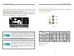
Fig. 5-2
Power off
Sleeping
AC Normal
Td Waiting
Td=10-20S
Standing-by
Power generating
Fault/protection recovery Th self-detecting
Th=60-70S
Device fault/environmental abnormity
Fault/
Pr
otectio
n
Device fault/environmental
abnormity
Fault/protection
recovery
Th=self-detect
Th=60-70S
5.4 Inverter working mode
5.3.3 Device management
Human-machine interaction
Human-machine interaction
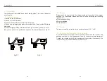
Warning
The safety standard for the inverter can not be modified
accord the modified standard shall comply with the local grid
standard, and the safety standard setting must be
performed by a qualified electrical engineer who is familiar
with Song series inverter and the local power grid. A wrong
safety standard setting may cause some damage of device
or cancellation of grid connecting license, and in this case
Xinqi Power will take no consequential responsibility.
5.3.2 Parameter setting
1) Serial port setting: select the serial port number for device communication.
2) Device selecting: select the device to be set.
3) Time setting: set the time of the current device.
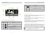
5.3.1 Main interface
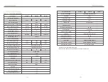
3) Current device current data curve.
2) Accumulated data displaying zone: current power generated, current day
power generated, total power generated,CO2/SO2 reduction and coal
equivalent.
1) Device list zone: names of all registered devices with the communication
status (LIVE or OFF) are displayed by a module tree, and one of the device can
be selected as the current device by clicking.
1) Device registration: a new device can be added into the device list by the
user.
2) Device modification: the name of a registered device can be modified by the
user.
3) Device deletion: a dismantled device can be deleted from the device list by the
user.
After the inverter is started up, the normal working state will be switched as per
the chart below:
DC1<70v & DC2<70v
DC1<100v & DC2<100v
DC1>100v or DC2>100v
DC1>100v or DC2>100v


