background image

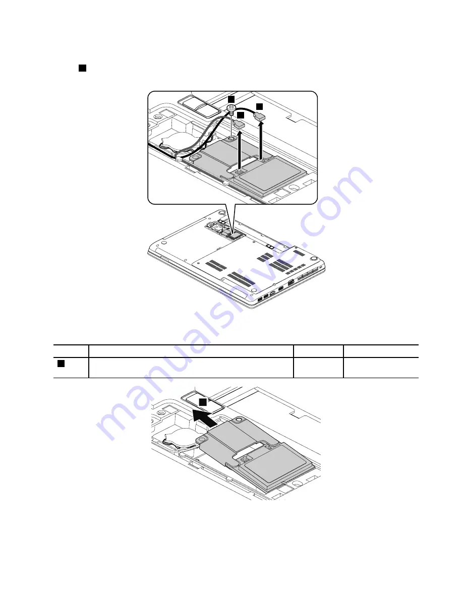
Removal steps of the PCI Express Mini Card for wireless LAN and the wireless LAN card bracket

In step

1

, unplug the connectors by using the antenna RF connector removal tool or pick the connectors

with your fingers and gently unplug them as shown.

1

1

2

When installing:

Plug the gray cable into the connector marked

MAIN

or

M

, and the black cable into the

connector marked

AUX

or

A

on the card.

Step

Screw (quantity)

Color

Torque

2

M2 × 3 mm, wafer-head, nylon-coated (1)

Black

0.181 Nm
(1.85 kgf-cm)

3

Chapter 9

.

Removing or replacing a FRU

69

Summary of Contents for Edge E445

Page 1: ...Hardware Maintenance Manual ThinkPad Edge E445...

Page 2: ...nder Appendix A Notices on page 101 First Edition June 2013 Copyright Lenovo 2013 LIMITED AND RESTRICTED RIGHTS NOTICE If data or software is delivered pursuant a General Services Administration GSA c...

Page 3: ...disc set 33 Using the Windows recovery programs on the Windows 8 operating system 34 Passwords 36 Power on password 37 Hard disk password 37 Supervisor password 37 How to remove the power on password...

Page 4: ...bly 82 1160 Card reader subcard 84 1170 Power button sub card 84 1180 I O sub card with USB connector and audio jack 85 1190 RJ45 sub card 87 1200 LCD unit 89 1210 Base cover assembly and DC in connec...

Page 5: ...hoot problems Important This manual is intended only for trained service technicians who are familiar with ThinkPad products Use this manual along with the advanced diagnostic tests to troubleshoot pr...

Page 6: ...iv Hardware Maintenance Manual...

Page 7: ...quipment unsafe Before you start the machine make sure that other service technicians and the customer s personnel are not in a hazardous position Place removed covers and other parts in a safe place...

Page 8: ...n working with powered on electrical equipment keep the other hand in your pocket or behind your back CAUTION An electrical shock can occur only when there is a complete circuit By observing the above...

Page 9: ...d the power cord disconnected Checklist 1 Check exterior covers for damage loose broken or sharp edges 2 Turn off the computer Disconnect the power cord 3 Check the power cord for a A third wire groun...

Page 10: ...rovide protection that meets the specific service requirement Note The use of a grounding system to guard against ESD damage is desirable but not necessary Attach the ESD ground clip to any frame grou...

Page 11: ...DANGER DANGER DANGER DANGER DANGER DANGER Chapter 1 Safety information 5...

Page 12: ...DANGER 6 Hardware Maintenance Manual...

Page 13: ...PERIGO PERIGO PERIGO Chapter 1 Safety information 7...

Page 14: ...PERIGO PERIGO PERIGO PERIGO PERIGO 8 Hardware Maintenance Manual...

Page 15: ...DANGER DANGER DANGER DANGER DANGER Chapter 1 Safety information 9...

Page 16: ...DANGER DANGER DANGER VORSICHT VORSICHT 10 Hardware Maintenance Manual...

Page 17: ...VORSICHT VORSICHT VORSICHT VORSICHT VORSICHT VORSICHT Chapter 1 Safety information 11...

Page 18: ...12 Hardware Maintenance Manual...

Page 19: ...Chapter 1 Safety information 13...

Page 20: ...14 Hardware Maintenance Manual...

Page 21: ...Chapter 1 Safety information 15...

Page 22: ...16 Hardware Maintenance Manual...

Page 23: ...al translations The laser compliance statements in this section are provided in the following languages English Arabic Brazilian Portuguese French German Hebrew Japanese Korean Spanish Traditional Chi...

Page 24: ...18 Hardware Maintenance Manual...

Page 25: ...Chapter 1 Safety information 19...

Page 26: ...20 Hardware Maintenance Manual...

Page 27: ...Chapter 1 Safety information 21...

Page 28: ...22 Hardware Maintenance Manual...

Page 29: ...talled before you replace any FRUs listed in this manual After a system board is replaced ensure that the latest UEFI BIOS is loaded to the system board before you complete the service action To downl...

Page 30: ...y for replacing FRUs for CTO special bid model and standard model This topic provides information about the model types and FRU identification Product definition This topic introduces different model...

Page 31: ...Status Lookup page click Parts Lookup 5 Type your machine type and serial number and then click Submit eSupport also can be used to view the general FRU list for a product To get the general FRU list...

Page 32: ...26 Hardware Maintenance Manual...

Page 33: ...othing to do with a hardware defect such as cosmic radiation ESD or software errors Consider replacing a FRU only when a problem recurs If you suspect that a FRU is defective clear the error log and r...

Page 34: ...ith the ThinkPad notebook computer Note The diagnostic tests are intended to test only ThinkPad products The use of non ThinkPad products prototype cards or modified options can lead to false indicati...

Page 35: ...e devices To run the UEFI diagnostic program do the following 1 Turn on the computer If the computer cannot be turned on go to Power system checkout on page 30 and check the power sources If an error...

Page 36: ...m checkout on page 30 and check the power sources If an error code is displayed go to Symptom to FRU index on page 39 for error code descriptions and troubleshooting hints 2 Insert the CD into the opt...

Page 37: ...emaining in the computer 1 If the battery status indicator does not turn on remove the battery pack and let it return to room temperature 2 Reinstall the battery pack 3 If the indicator still does not...

Page 38: ...e battery pack If the resistance is correct replace the system board Checking the backup battery Do the following 1 Power off the computer and unplug the ac power adapter from it 2 Turn the computer u...

Page 39: ...p onto removable media or a network drive before you start the recovery process The recovery process takes one to two hours to complete The length of time depends on the method you use If you use prod...

Page 40: ...er without losing your personal files or changing your settings Attention If you refresh your computer the programs that came with your computer and the programs that you installed from Windows Store...

Page 41: ...very environment starts automatically Then you can choose repair and recovery options by following the instructions on the screen Note Ensure that your computer is connected to ac power during the rec...

Page 42: ...t start your computer or if you cannot start the Windows recovery image on your computer use recovery media to recover your computer To use recovery media do the following Note Ensure that your comput...

Page 43: ...replaced for a scheduled fee For instructions on how to remove the hard disk password see How to remove the hard disk password on page 38 Supervisor password A supervisor password protects the system...

Page 44: ...ogo is displayed immediately press F1 to enter the ThinkPad Setup program 3 Select Security 4 Select Password 5 Select Hard disk x password where x is the letter of the hard disk drive A pop up window...

Page 45: ...If you have defined one of the following actions as the event that causes the system to go into hibernation mode perform that action Closing the lid Pressing the power button Also the computer goes i...

Page 46: ...The access to EEPROM is failed Replace the system board 0188 Invalid RFID Serialization Information Area Replace the system board 0189 Invalid RFID configuration information area The EEPROM checksum i...

Page 47: ...ni SATA device 2 Replace the mini SATA device 3 Replace the system board 2110 Read error on HDD0 Main HDD 1 Reseat the hard disk drive 2 Replace the main hard disk drive 3 Replace the system board 211...

Page 48: ...t beeps pause one short beep pause one more short beep pause and three short beeps Remove the device from Express Card slot One long and two short beeps Replace the system board Five short beeps Repla...

Page 49: ...board Horizontal or vertical lines displayed on LCD LCD assembly Intermittent problems Intermittent system hang problems can be due to a variety of causes that have nothing to do with a hardware defec...

Page 50: ...connect the removed devices one at a time until you find the failing FRU 7 If the problem remains replace the following FRUs one at a time do not replace a nondefective FRU a System board b LCD assemb...

Page 51: ...us Green The ac power adapter is connected Off The ac power adapter is not connected 3 System status 4 System status The illuminated dot in the ThinkPad logo on the outer lid of the computer and on th...

Page 52: ...46 Hardware Maintenance Manual...

Page 53: ...location F6 Press this key to switch between the computer display and an external monitor The following options will be displayed Computer display only LCD Computer display and external monitor same i...

Page 54: ...ed You can quickly change the state of each feature on the list Notes If you want to use this button to enable or disable the wireless features the following device drivers must be installed on your c...

Page 55: ...1 2 3 4 5 9 6 7 8 10 11 12 13 14 1 Microphones 8 System status indicator1 2 Camera 9 Media card reader slot 3 ac power connector 10 Touch pad 4 RJ45 Ethernet connector 11 TrackPoint buttons 5 Optical...

Page 56: ...5 1 Small bottom cover1 4 Large bottom cover2 2 Battery pack latches 5 Built in stereo speakers 3 Battery pack 1 The wireless LAN card is located underneath the small bottom cover 2 The memory modules...

Page 57: ...lick User Guides Manuals and then follow the on screen instructions to find the manual for your product You might be required to return the defective CRU When return is required 1 return instructions...

Page 58: ...Major FRUs and CRUs 1 2 3 4 5 6 7 8 9 10 11 12 13 14 15 16 17 18 19 20 21 22 23 24 52 Hardware Maintenance Manual...

Page 59: ...ck Yes No 9 RJ45 sub card No No 10 DC in connector No No 11 Optical drive or blank bezel Yes No 12 I O sub card with USB connector and audio jack No No 13 Small bottom cover Yes No 14 Large bottom cov...

Page 60: ...LCD FRUs and CRUs 6 7 2 3 4 2 3 4 6 7 5 1 1 1 54 Hardware Maintenance Manual...

Page 61: ...ts and other FRUs Table 11 Miscellaneous parts FRU description Self service CRU Optional service CRU Rubber cap LCD Rubber screw cap 4 No No Screw kit Screw kit No No Table 12 Other FRUs FRU descripti...

Page 62: ...56 Hardware Maintenance Manual...

Page 63: ...ipping label and a container will be included with the replacement CRU and 2 you might be charged for the replacement CRU if Lenovo does not receive the defective CRU within thirty 30 days of your rec...

Page 64: ...ber by doing the following 1 Install the latest version of LENOVO ThinkPad Hardware Maintenance Diskette or Maintenance Key and then restart the computer 2 From the main menu select 1 Set system ident...

Page 65: ...em board The electronic storage of this information simplifies the procedure to check if the ECA has been previously applied to a machine The machine does not need to be disassembled to check for the...

Page 66: ...date select 4 Write box build date from EEPROM and follow the instruction on the screen If the system board is being replaced try to read the ECA information from the old system board and transfer the...

Page 67: ...he following general guidelines 1 Do not try to service any computer unless you have been trained and certified An untrained person runs the risk of damaging parts 2 Before replacing any FRU review Ch...

Page 68: ...computer the customer should download this program before a non physically damaged battery pack is replaced Note that a physically damaged battery pack is a non warranty replacement part Removal step...

Page 69: ...1 and then remove the large bottom cover 2 1 2 1 1 When installing Attach the large bottom cover as shown in the following illustration 1030 Small bottom cover For access remove this FRU 1010 Battery...

Page 70: ...the small bottom cover 2 2 1 When installing Attach the small bottom cover as shown in the following illustration 1040 Optical drive or blank bezel For access remove these FRUs in order 1010 Battery p...

Page 71: ...p Screw quantity Color Torque 1 M2 3 mm wafer head nylon coated 1 Black 0 181 Nm 1 85 kgf cm 3 2 1050 Memory modules For access remove these FRUs in order 1010 Battery pack on page 62 1020 Large botto...

Page 72: ...into place Ensure that the memory module is firmly installed in the slot and does not move easily 1060 Hard disk drive assembly For access remove these FRUs in order 1010 Battery pack on page 62 1020...

Page 73: ...assembly 2 1 1 2 Step Screw quantity Color Torque 1 M2 3 mm wafer head nylon coated 2 Black 0 181 Nm 1 85 kgf cm 3 When installing Make sure that the hard disk drive assembly is attached firmly Chapt...

Page 74: ...or Torque 1 M3 3 mm wafer head nylon coated 4 Silver 0 392 Nm 4 kgf cm 1070 PCI Express Mini Card for wireless LAN and wireless LAN card bracket For access remove these FRUs in order 1010 Battery pack...

Page 75: ...al tool or pick the connectors with your fingers and gently unplug them as shown 1 1 2 When installing Plug the gray cable into the connector marked MAIN or M and the black cable into the connector ma...

Page 76: ...ge 62 1030 Small bottom cover on page 63 Removal steps of the backup battery DANGER Use only the authorized battery specified for your computer Any other battery could ignite or explode 1 2 When insta...

Page 77: ...he screws 2 2 2 2 1 When installing Make sure that the connector is attached firmly to the system board 3 When installing Do not press the top of the fan cover and the fan hub 1100 Thermal pipes For a...

Page 78: ...n handling the thermal fan assembly Do not touch or hold any part of the thermal fan or thermal pipes with bare fingers Before you attach the thermal pipes to the computer apply thermal grease at an a...

Page 79: ...of the thermal fan assembly Do not press the heat pipe Hold both sides of the heat pipe if you need to take the thermal fan assembly Do not shake or drop the thermal fan assembly Ensure that the fan...

Page 80: ...l steps of the keyboard 1 1 When installing Make sure that the screws are fastened and the keyboard is secured Step Screw quantity Color Torque 1 M2 8 mm wafer head nylon coated 2 Black 0 181 Nm 1 85...

Page 81: ...3 4 4 4 4 7 8 6 5 Installation steps of the keyboard To install the keyboard do the following 1 Attach the connectors Chapter 9 Removing or replacing a FRU 75...

Page 82: ...keyboard toward you until the keyboard is in place 4 Secure the keyboard by tightening the screws from the bottom side of the computer 1120 Keyboard bezel For access remove these FRUs in order 1010 Ba...

Page 83: ...antity Color Torque 1 M2 8 mm wafer head nylon coated 10 Black 0 181 Nm 1 85 kgf cm 2 M2 3 mm wafer head nylon coated 4 Black 0 181 Nm 1 85 kgf cm 3 Step Screw quantity Color Torque 3 M2 5 mm wafer he...

Page 84: ...ely remove the keyboard bezel 11 11 11 11 11 11 11 11 11 11 11 1130 Microprocessor For access remove these FRUs in order 1010 Battery pack on page 62 1020 Large bottom cover on page 62 1090 Thermal fa...

Page 85: ...G forces are applied Note Dropping a system board from a height of as little as 6 inches so that it falls flat on a hard bench can subject the accelerometer to as much as 6000 G s of shock Be careful...

Page 86: ...090 Thermal fan on page 71 1100 Thermal pipes on page 71 1110 Keyboard on page 73 1120 Keyboard bezel on page 76 1130 Microprocessor on page 78 Removal steps of the system board Attention The followin...

Page 87: ...For models with an integrated thermal module b a 3 4 1 2 6 5 When installing Make sure that the connectors are attached firmly to the system board Chapter 9 Removing or replacing a FRU 81...

Page 88: ...r 1010 Battery pack on page 62 1020 Large bottom cover on page 62 1030 Small bottom cover on page 63 1040 Optical drive or blank bezel on page 64 1060 Hard disk drive assembly on page 66 1070 PCI Expr...

Page 89: ...uantity Color Torque 1 M2 2 mm wafer head nylon coated big head 3 Black 0 181 Nm 1 85 kgf cm 2 2 When installing Attach the speaker assembly and route the cable as shown in the following figure and ma...

Page 90: ...l on page 76 Removal steps of card the reader sub card 1 2 Step Screw quantity Color Torque 1 M2 3 mm wafer head nylon coated 1 Black 0 181 Nm 1 85 kgf cm 1170 Power button sub card For access remove...

Page 91: ...cm 1180 I O sub card with USB connector and audio jack For access remove these FRUs in order 1010 Battery pack on page 62 1020 Large bottom cover on page 62 1040 Optical drive or blank bezel on page...

Page 92: ...connector and audio jack 1 2 3 When installing Make sure that the connector is attached firmly to the system board Step Screw quantity Color Torque 3 M2 5 mm wafer head nylon coated 1 Silver 0 181 Nm...

Page 93: ...order 1010 Battery pack on page 62 1020 Large bottom cover on page 62 1040 Optical drive or blank bezel on page 64 1060 Hard disk drive assembly on page 66 1110 Keyboard on page 73 1120 Keyboard beze...

Page 94: ...b card 1 2 3 When installing Make sure that the connector is attached firmly to the system board Step Screw quantity Color Torque 3 M2 5 mm wafer head nylon coated 1 Silver 0 181 Nm 1 85 kgf cm 4 4 88...

Page 95: ...6 1070 PCI Express Mini Card for wireless LAN and wireless LAN card bracket on page 68 1110 Keyboard on page 73 1120 Keyboard bezel on page 76 1190 RJ45 sub card on page 87 Removal steps of the LCD un...

Page 96: ...In step 3 release the wireless antenna cables from the cable guides 3 3 3 3 3 3 3 3 3 3 4 90 Hardware Maintenance Manual...

Page 97: ...In step 5 release wireless antenna cables from the cable guides 5 5 5 6 6 1210 Base cover assembly and DC in connector For access remove these FRUs in order Chapter 9 Removing or replacing a FRU 91...

Page 98: ...rmal fan on page 71 1100 Thermal pipes on page 71 1110 Keyboard on page 73 1120 Keyboard bezel on page 76 1140 System board assembly on page 79 1150 Speaker assembly on page 82 1170 Power button sub c...

Page 99: ...labels to the base cover The new base cover FRU is shipped with a kit containing labels of several kinds The following illustration shows the correct location of each label Chapter 9 Removing or repl...

Page 100: ...razil ANATEL label for wireless LAN card 6 Japan warning US battery label 16 Non encryption label 8 Asset tag 17 China GEO label 9 Israel homologation label for 3G 18 China CECP label 10 Israel homolo...

Page 101: ...Color Torque 1 M2 4 5 mm wafer head nylon coated 4 with screw caps Silver 0 392 Nm 4 kgf cm 2 2 2 2 2 2 2 2 2 2 When installing Make sure that all the latches are attached firmly Then secure the beze...

Page 102: ...I Express Mini Card for wireless LAN and wireless LAN card bracket on page 68 1110 Keyboard on page 73 1120 Keyboard bezel on page 76 1190 RJ45 sub card on page 87 1200 LCD unit on page 89 2010 LCD be...

Page 103: ...with dual microphones For access remove these FRUs in order 1010 Battery pack on page 62 1020 Large bottom cover on page 62 1030 Small bottom cover on page 63 1040 Optical drive or blank bezel on page...

Page 104: ...e 95 Removal steps of the camera 2 1 Step Screw quantity Color Torque 2 M2 3 mm wafer head nylon coated small head 1 Black 0 181 Nm 1 85 kgf cm When installing Make sure that the connector is attached...

Page 105: ...eless LAN and wireless LAN card bracket on page 68 1110 Keyboard on page 73 1120 Keyboard bezel on page 76 1190 RJ45 sub card on page 87 1200 LCD unit on page 89 2010 LCD bezel assembly on page 94 202...

Page 106: ...following illustration Attention When you route the cables ensure that they are not subject to any tension Tension could cause the cables to be damaged by the cable guides or a wire to be broken a Wi...

Page 107: ...publication Lenovo may make improvements and or changes in the product s and or the program s described in this publication at any time without notice The products described in this document are not...

Page 108: ...ice marks of others Abbreviation table The following table lists all abbreviations used in this manual Abbreviation Term 3G The 3rd Generation Telecommunication BGA Ball Grid Array BIOS Basic Input Ou...

Page 109: ...twork LCD Liquid Crystal Display MAC Media Access Control MT Machine type MTM Machine type and model PC Personal Computer PCH Platform Controller Hub POST Power on self test RAM Random Access Memory R...

Page 110: ...104 Hardware Maintenance Manual...

Page 111: ......

Page 112: ...Part Number 0C11030 Printed in China 1P P N 0C11030...

Page 113: ...1P0C11030...

Reviews: