background image


 T9901018-1 

Page 22 of 26 

Vacuum clean and remove any build-up of dust, dirt and debris within the dry cooling unit, 
especially on the cooling coil. 
 

Note: Fan motors are permanently lubricated and require no additional lubrication. 


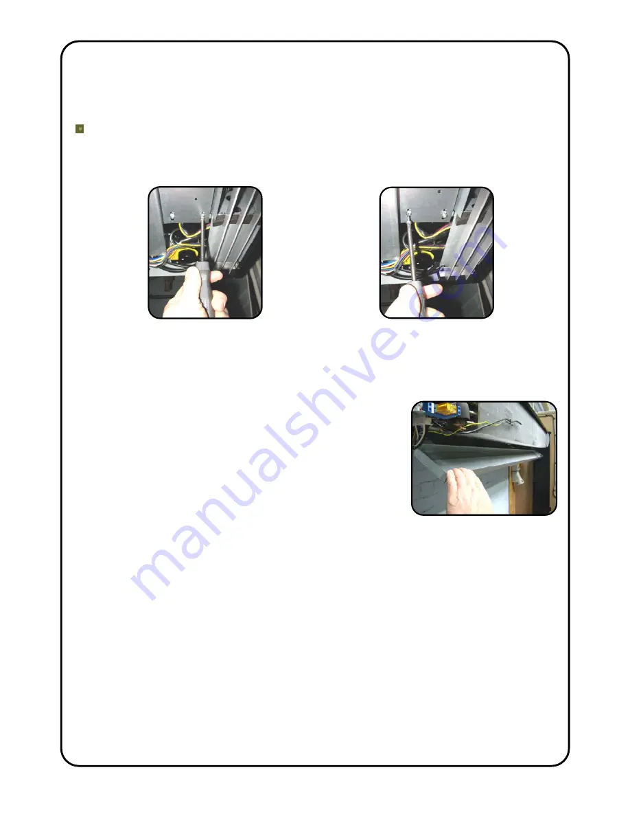
If the Dry Cooling Unit has been condensing during the last service interval :- 
   (e.g. has experienced an emergency situation) 

 
Unclip the condensate pipe at the right hand rear of the dry cooling unit. 


The drain tray now angles down along its front edge and the 
inside surface of the tray can be easily cleaned. Remove all 
debris from the drain tray, outlet spout and condensate hose. 

BEWARE

 of sharp metal fins on the cooling coil ! 

 
Check there are no kinks in condensate hoses. If the 
condensate pump is a peristaltic type change the rubber 
pump head tube. 
 
If the dry cooling unit has been condensing it is important to find out why this has been 
happening and correct the situation. It may be that there has been a failure in the air 
conditioning on site or environmental conditions in the server room have gone above 
24°C/40%Rh due to some other circumstance, e.g. doors left open, extreme weather 
conditions. 
 
Once the dry cooling unit has been cleaned, visually inspect the cooling unit 
components. Ensure the two temperature sensors are located correctly on the front face 
of the cooling coil (see Section – Commissioning, Page 16). Check all electrical 
connections and terminals within the unit are tight and that crimp connections have not 
become loose. 
 
Refit the drain tray (if released), bottom access panel and air inlet grilles with air filters. 
Switch on the electrical supplies and fully function test the dry cooling unit to ensure 
correct operation (see Section – Commissioning, Page 16). Check the condensate 
pump operates, if fitted. 

Loosen by 3 turns, the rear row of 
drain tray fixing screws along the 
whole length of the tray. Do not 
remove these screws completely. 

Remove the front row of drain tray 
fixing screws along the whole 
length of the drain tray. Keep the 
screws. 

Summary of Contents for PHV2000NT

Page 1: ...NCE INSTRUCTIONS For use with PUHZ HW140VHA2 or YHA2 Outdoor Units PLEASE READ THESE INSTRUCTIONS CAREFULLY BEFORE ATTEMPTING INSTALLATION Thermoscreens Ltd St Mary s Road Nuneaton Warwickshire Englan...

Page 2: ...allation items supplied and fitted by installer Thermoscreens PHV2000NT Dry Cooling Unit Mitsubishi Electric PUHZ HW140 Outdoor Unit Permanent 1 phase mains electrical supply Siemens RDG400 Manual Roo...

Page 3: ...sed unvented water system must be used for the flow and return water pipework between the Thermoscreens dry cooling unit and the Mitsubishi Electric outdoor unit This should incorporate water pump s e...

Page 4: ...his should be connected to the 15mm copper drain pipe that protrudes from the right hand rear of the cooling unit behind the plastic end cap Condensate pumps are not recommended but if a gravity drain...

Page 5: ...is to provide warning of elevated room air temperatures which could indicate a fault in the air conditioning system or some other problem This thermostat can be set during commissioning to between 15...

Page 6: ...chase is necessary so please keep a copy of your invoice IMPORTANT This Dry Cooling Unit is intended only for use with a Mitsubishi Electric PUHZ HW140VHA2 or YHA2 Air to Water Outdoor Unit These inst...

Page 7: ...fixing system not supplied needs to be used to fix the brackets to the wall taking into account the type of wall and the weight of the unit 76kg Step 1 Refer to Figure 1 Page 8 for mounting details an...

Page 8: ...c 150 min 6 x M10 threaded holes for M10 drop rods IMPORTANT Use all 6 drop rod holes 3 Holes x 20mm Water Connections Rp1 56 70 1in BSP Internal Emergency Condensate Connection at rear of plastic end...

Page 9: ...ure plus two in the centre and pull the panel out forwards Chilled Water Pipework Left hand side of unit This should ideally be carried out before connection of any electrical and controls cables The...

Page 10: ...nal pipework if used must be weather wrapped or installed in suitable trunking Condensate Disposal System Right hand side of unit As explained in Section Design Information Page 3 the dry cooling unit...

Page 11: ...l accept a 10mm diameter condensate sensor Different size grommets can be fitted to suit other condensate sensors or if the grommet is removed a larger condensate sensor can be located in the 13mm dia...

Page 12: ...Power Input kW rating of water pump installed 2 7A for cooling unit Rated Current Amps of water pump installed max 2A IMPORTANT Please note that the water pump is supplied and fitted by the installer...

Page 13: ...TB62 5 6 A B Brown Blue PUHZ HW140VHA2 YHA2 Unit Error Signal Volt Free Output FAN MOTORS SIEMENS RDG400 MANUAL ROOM CONTROL CN20 RED Link Fitted L2 L1 N E CNS2 Mitsubishi sensor fitted in pocket of f...

Page 14: ...onnection 8 Mitsubishi Electric heat pump system Error Signal volt free contacts rated 1A max Error Closed 9 Terminal on Dry Cooling Unit Optional Room Over Temperature Alarm Volt Free contacts rated...

Page 15: ...picture NB For clarity the site wiring to terminals 6 to 12 for the optional items Remote ON OFF Mitsubishi Error Signal Room Over Temperature Alarm is not shown in this picture Please note All the pa...

Page 16: ...nstallation debris is removed see BSRIA AG 1 2001 1 Check that the chilled water system has been filled and the correct concentration of inhibitor has been added If necessary check that the system has...

Page 17: ...there is site wiring between terminals 4 5 in the dry cooling unit and terminals M B1 in the Siemens RDG400 manual room control the room air temperature will be measured using the black return air tem...

Page 18: ...k there is no mechanical noise coming from the fans and that both fans work If there is a Remote On Off wired into terminals 6 7 on the dry cooling unit switch this On Check that the LCD display scree...

Page 19: ...condensate pump is being used ensure this is operating correctly and if possible simulate a pump alarm fault condition to check that the alarm will function Some condensate pumps may require distilled...

Page 20: ...ill then flash this target temperature 5 times and go back to showing the air temperature If the target temperature is lower than the air temperature the outdoor unit and the water pump s will start t...

Page 21: ...Always disconnect and isolate the mains electricity supply both at the local electrical supply to the Thermoscreens Dry Cooling Unit and at the Mitsubishi Electric Outdoor Unit before servicing maint...

Page 22: ...ituation It may be that there has been a failure in the air conditioning on site or environmental conditions in the server room have gone above 24 C 40 Rh due to some other circumstance e g doors left...

Page 23: ...ns dry cooling unit using a damp cloth Do not use scouring cream products Visually inspect the pipe work system for water leaks and repair as necessary Check the condition of the pipework insulation a...

Page 24: ...temperature down NB Dry cooling unit will only cool if room air temperature is above the target temperature Room temperature is low Air Inlet Sensor is measuring low air temperature so target tempera...

Page 25: ...re they are correct although Thermoscreens Ltd disclaims all liability for damage resulting from any inaccuracies and or deficiencies in this documentation Thermoscreens Ltd retain the right to change...

Page 26: ...Series Type PHV2000 NT used with Mitsubishi Electric PUHZ HW140VHA YHA VRF PHV2000 NT used with Mitsubishi Electric PWFY P200VM E AU Relevant EC Council the Machinery Directive 2006 42 EC the Low Vol...

Reviews: