background image

INSTALLATION, USE AND MAINTENANCE GUIDE 

POPSTAR 6 

– POPSTAR 10


Page 

33


ENG 


10 

 ALARMS 

The appliance is programmed to communicate 7 alarms. 
 

ATTENTION:

 The appearance of one of the alarms described below, does not necessarily imply a defect in the product, 

but  simply  Thermorossi  S.p.A.’s  intention  to  inform  the  user  of  the  need  for corrective  actions  in  order  to  guarantee 
maximum safety, greater reliability and high performance of the appliance. 
 

The alarms are listed below: 


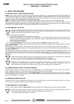
This meassge appears when during the 

WORK

 stage the temperature of the smoke drops below a preset threshold: this means that 

the appliance is shutting off due to lack of pellets. To reset the alarm the power to the appliance must be switched off then on by 
turning the switch 0-1 located on the power panel. 

It is mandatory to empty and clean the brazier

, and then to fill the pellet tank 

before repeating the START phase. It could be that the screw feeder is completely empty, so the start up sequence may have to be 
carried out twice. 


This appears if, after the 

START

 sequence, the smoke has not reached a suitable temperature. To reset the alarm the power to the 

appliance must be switched off then on by turning the switch 0-1 located on the power panel. 

It is mandatory to empty and clean the brazier

 before repeating the START phase: pellets emptied from the brazier must not be 

fed into the tank. 


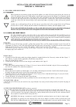
This occurs when the smoke outlet is partially blocked. To reset the alarm the power to the appliance must be switched off then on 
by turning the switch 0-1 located on the power panel. 
Before restarting the appliance check for any irregularities such as blocked flue outlet, open firebox door, very dirty appliance. 

Do not 

start up the appliance until the problem has been identified and solved


It is mandatory


to empty and clean the brazier 

before repeating the START phase:


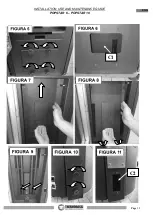
This appears when the appliance overheats. 

After having verified and solved 

the causes for the overtemperature, unscrew the 

plastic cover of the reset thermostat located on the power/control panel and press the button (the appliance can only be reset when 
its temperature has dropped considerably). To 

reset the alarm 

the power to the appliance must be switched off then on by turning 

the switch 0-1 located on the power panel. 

It is mandatory


to empty and clean the brazier 

before repeating the START phase: 


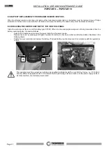
Appears when the smoke thermocouple is damaged or absent. Contact the technical assistance service 


Activates when the smoke suction unit revolution sensor detects a very slow rotation speed: check the flue pipes and the flue outlet. 
If the problem persists contact the technical assistance service. 


Trips when the smoke suction unit revolution sensor fails to detect any rotation. The smoke suction unit or the rotation sensor are not 
working. Contact the technical assistance service. 


Summary of Contents for POPSTAR 10

Page 1: ...Installation use and maintenance guide Models POPSTAR 6 POPSTAR 10 ...

Page 2: ...INSTALLATION USE AND MAINTENANCE GUIDE POPSTAR 6 POPSTAR 10 Page 1 ENG Installation use and maintenance guide ...

Page 3: ...RAWING COMBUSTION AIR FROM OUTSIDE 16 5 DESCRIPTION OF THE CONTROLS 17 5 1 DESCRIPTION OF THE CONTROL PANEL 17 5 2 DESCRIPTION OF THE POWER PANEL 18 5 3 DATE SETTING THE DATE AND TIME 19 5 4 CHRONO ON OFF PROGRAMMING 19 5 5 LEVEL OPERATING LEVEL SETTING 21 5 6 ROOM CONTROL CONNECTION WITH THE ROOM CONTROL DEVICE OPTIONAL 22 5 7 SHOW CRONO ON OFF PROGRAMMING DISPLAY 22 6 USE OF THE APPLIANCE 23 6 1...

Page 4: ...REWORD 30 9 2 ROOM VENTILATION 30 9 3 SMOKE OUTLET 30 9 3 1 CHIMNEY TYPES 30 9 3 2 FLUE OUTLET FLUE SYSTEM COMPONENTS 31 9 3 3 CONTROLS PRIOR TO INSTALLING THE APPLIANCE 31 10 ALARMS 33 11 ELECTRICAL WIRING 34 12 INFORMATION FOR THE SKILLED TECHNICIAN 35 12 1 MAIN COMPONENTS AND THEIR OPERATION 35 12 2 REQUIREMENTS NECESSARY FOR CORRECT OPERATION 35 12 3 TROUBLESHOOTING CAUSE SOLUTION 35 ...

Page 5: ...ant Article 11 5 THERMOROSSI S P A Via Grumolo n 4 36011 Arsiero VI 5 Nome e indirizzo del mandatario ai sensi dell articolo 12 paragrafo 2 Name and address of the agent as required pursuant Article 12 2 6 Sistema di valutazione e verifica della costanza della prestazione del prodotto da costruzione di cui all allegato V Sistema 3 e 4 System of assessment and verification of constancy of performan...

Page 6: ...ale Nominal heat output Potenza termica resa in ambiente Room heating output Potenza termica ceduta all acqua Water heating output 9 63 kW 9 63 kW kW Rendimento Efficiency 94 20 alla potenza termica nominale Nominal heat output 96 69 alla potenza termica ridotta Reduced heat output 9 La prestazione del prodotto di cui ai punti 1 e 2 è conforme alla prestazione dichiarata di cui al punto 8 Signatur...

Page 7: ...pliance DAMAGE TO PROPERTY This safety symbol identifies messages or instructions that are fundamental for the appliance and system to function well To avoid serious damage to the appliance adhere strictly to these instructions INFORMATION This symbol indicates important instructions for good functioning of the appliance If this information is not correctly observed the performance of the applianc...

Page 8: ... the Fire Department Mandatory signalling and safety distances and the Note concerning installation of heaters issued by the Association of Cantonal Fire Agencies VKF AEAI ATTENTION it is mandatory to earth the appliance If this instruction is not observed serious damage which is not covered by warranty will result to the body of the appliance Have an electrician check the earthing There must be n...

Page 9: ... 69 CO emissions with 13 O2 at rated power mg m3 73 111 CO emissions with 13 O2 at reduced power mg m3 452 452 Power supply voltage and frequency V Hz 230 50 230 50 Max electrical consumption A W 1 52 350 1 52 350 Min electrical consumption A W 0 11 25 0 11 25 Heatable volume m3 170 260 All the data are based on the stove fuelled with standards UNI EN 14961 2 A1 and A2 type approved pellets Import...

Page 10: ...t is normal to find some pellets remaining in the tank even if the stove shuts off because the pellets have run out Attention when filling up the tank take care not to drop any pellets into the internal parts of the appliance as in extreme cases this could generate live flames The manufacturer recommends emptying the tank and vacuuming the screw feeder zone once a month and during the summer perio...

Page 11: ...ntaining the type of materials utilised b Project as defined in Article 5 of Ministerial Decree n 37 22 January 2008 c Drawing of the finished installation d References to existing partial or previous declarations of conformity e g electrical wiring e Copy of the certificate of recognition of the professional technical qualifications These documents must by law be kept together with the use and ma...

Page 12: ... the side panel and fit the 4 fasteners in the corresponding slots If it is not sufficiently fastened to the appliance remove it and pull out even further the tabs indicated with the letter B Next proceed to install the opposite side panel 4 Remove the profile F after undoing the three screws G and insert the lower panel E 5 Then return the previously removed profile F to its place 6 Adjust the up...

Page 13: ...dicated with the letter B Next proceed to install the opposite side panel 4 Seal the upper glass elements with high temperature silicone taking care to position them correctly as indicated in the figure 5 Remove the profile F after undoing the three screws G and insert the lower panel E 6 Then return the previously removed profile F to its place 7 Adjust the upper and lower pin D and the lower and...

Page 14: ...her the tabs indicated with the letter B Next proceed to install the opposite upper side panel 4 Seal the upper half moon shaped elements with high temperature silicone taking care to position them correctly as indicated in the figure 5 Remove the profile F after undoing the three screws G and insert the lower panel E 6 Then return the previously removed profile F to its place 7 Adjust the upper a...

Page 15: ...oled off and disconnected from electric power Once you have completed this operation be sure to remove the handle to avoid accidental opening of the door and place it on the dedicated hook D 4 7 CONTROL PANEL The front panel of the concealed control panel is installed on the right side of the appliance To open it simply pull the panel outwards To close it push it in Emissione 21 07 2020 Revisione ...

Page 16: ...s disconnected from the electrical power socket REAR SMOKE OUTLET If you choose to use the smoke outlet at the rear then loosen the two screws E and remove the side panel F by lifting it upwards Unscrew the knobs A and remove the bracket B Undo the screws on the collar C and the flange D and remove both elements Next interchange the positions of the collar C and the flange D secure them and ensure...

Page 17: ...chased the coaxial outlet kit Optional proceed as follows 1 Loosen the two screws P and remove the side panel Q by lifting it upwards 2 Use pliers to remove the pre cut profiles R 3 Fit the rubber collar O onto the outside of the combustion air exhaust pipe of the appliance 4 Insert the hose N in the rubber collar O and tighten it with the steel clamp M 5 Fit pipe L to the smoke outlet of the appl...

Page 18: ...thing to dry on the appliance When using a clothes horse keep at a suitable distance It is strictly prohibited to disconnect the appliance from the electrical power mains during normal operation 5 1 DESCRIPTION OF THE CONTROL PANEL The control panel is managed by a microprocessor The control buttons and the various displays are described below The control buttons are Clock button Press this button...

Page 19: ...ion power as the temperature increases which can be seen by the bars that light up around the symbol Once it has dropped below a certain threshold the room fan deactivates automatically Dashes appear along the top of the display and each dash corresponds to one day of the week set by the user e g 1 corresponds to Monday 2 corresponds to Tuesday etc The operating status of the appliance appears bel...

Page 20: ...to change the hour Once you have set the hour confirm the value by pressing the Flame Button Once confirmed the selector shifts to the flashing minutes section Press the Scroll Buttons to set the minutes Press the Flame button to confirm Once confirmed the date and time setting screen closes automatically and the initial screen returns to the display If you confirm the wrong value simply press the...

Page 21: ... for the second time ON2 Once the hour has been set confirm the value by pressing the Flame Button Once confirmed the selector shifts to the minute section of ON2 Press the Scroll Buttons to set the minutes for the second start up Confirm the value by pressing the Flame Button Now press the Scroll Buttons to select the hour at which you wish the appliance to shut off automatically OFF2 Once the ho...

Page 22: ...een to enable the appliance to carry out the ON OFF cycles as programmed simply press the Clock Button The text CR ON and the image of a clock will appear on the main screen The programmed cycles are now enabled When the programmed cycles are enabled a clock symbol appears on the display it will not be possible to use an additional chronothermostat see dedicated paragraph When the programmed cycle...

Page 23: ...y pressing the other Scroll Button To set the desired level or to exit the screen simply press the Menu Button the initial screen will appear on the display The level selection can be made with the appliance OFF or ON If the change is made while the appliance is running the difference in the flame will be apparent It is mandatory to pay particular care when selecting the most appropriate operating...

Page 24: ... Ventilation button repeatedly to set the six fan speeds the fan if enabled will only activate once the smoke has reached the preset temperature The electrical heater will start to overheat and only after a few minutes the first lot of pellets will start dropping into the brazier This occurs because the screw feeder has to fill up because it is completely empty At the first start up the appliance ...

Page 25: ...e operating principle is as follows When the room temperature reaches the set temperature only during the WORK phase the thermostat closes the contact and the appliance shifts to the minimum room fan speed if activated and minimum combustion power This condition is shown on the display with the flashing of the bar indicating ventilation if activated and the bar indicating combustion the appliance ...

Page 26: ...sibility for the life of the electrical heater if subjected to excessive start ups It is recommended not to set the desired room temperature or to set it at the highest possible value for the chronothermostat in order to avert this danger ATTENTION Use common type N O normally open contacts for the connection to the chronothermostat ATTENTION In the event of connections to the chronothermostat The...

Page 27: ...n the area around the spark plug ATTENTION make sure before every start up that the brazier is clean and in the correct position If necessary clean the burner more thoroughly using an ash vacuum device EVERY 3 DAYS Check that the holes of the burner and the heater lodging channels are completely sediment free If necessary vacuum and clean Figure 1 2 and 3 Remove if present all silica agglomerates ...

Page 28: ... appliance Any problems resulting from total or partial lack of cleaning or maintenance will immediately void the warranty ATTENTION if the appliance remains inactive and or unused for more than one month it is necessary to clean the entire appliance thoroughly as well as the smoke discharge tube and the flue outlet to remove any obstructions e g birds nests in the chimney cap before restarting A1...

Page 29: ...INSTALLATION USE AND MAINTENANCE GUIDE POPSTAR 6 POPSTAR 10 Page 28 ENG C1 C2 ...

Page 30: ...programming are not being memorised then the battery needs replacing Proceed as follows Switch off the appliance and unplug the power cable from the power source Remove the cover by pressing your fingers towards the centre in order to press the two tabs A and B as illustrated in the following figure Pull the top cover outwards and replace the battery The dead battery must be disposed of in complia...

Page 31: ... this position is not possible the section of the ventilation openings must be enlarged by at least 50 9 2 2 VENTILATION OF THE ADJACENT ROOMS The air flow can also be obtained from an adjacent room as long as the adjoining room is equipped with direct ventilation in compliance with the paragraphs described above only appliances connected to the exhaust pipe are installed in the room that is venti...

Page 32: ...ilure Failure to comply with these requirements may result in accumulation of smoke inside the firebox with possible explosions and or smoke escaping into the room The figures illustrate the best solution for discharging the smoke out through the roof or into the flue outlet If you prefer to exhaust the smoke from the roof insert a union tee with inspection cap connecting brackets suitable for the...

Page 33: ...pe must be made from suitable materials such as porcelain coated steel tubes and the various fittings sealed with red silicone resistant to 350 C The outer casing of the tube must be made with insulating material mineral wool ceramic fiber or use pre insulated tubing THE FLUE OUTLET MUST BE USED ONLY FOR THE APPLIANCE It must be possible to inspect and remove all the smoke tube sections for clean ...

Page 34: ...mptied from the brazier must not be fed into the tank This occurs when the smoke outlet is partially blocked To reset the alarm the power to the appliance must be switched off then on by turning the switch 0 1 located on the power panel Before restarting the appliance check for any irregularities such as blocked flue outlet open firebox door very dirty appliance Do not start up the appliance until...

Page 35: ...otto Sviluppo 1 1 TEL 0445 741310 FAX 0445 741657 Via Grumolo 4 36011 ARSIERO Vicenza ITALY S p A Spessore Approv Data approv Formato SCHEDA Cod Disegnatore Volume Peso Colore Revisione Descrizione Revisione Autore Data Descrizione LAMIERA Il fornitore è responsabile della corretta realizzazione del particolare come indicano le viste di progetto lo sviluppo piano deve essere verificato ed eventual...

Page 36: ...ses for the overtemperature havebeenidentifiedand remediedthe appliance canbe reactivated byunscrewingthe plasticcoverofthe thermostatlocated on the power panel and pressing the button the appliance temperature must have considerably dropped GLOW PLUG It is activated in the START phase Heats the air to 800 C which assist the first combustionofthepelletspresentinthe brazier The sparkplug is guarant...

Page 37: ...PLIANCE STARTS TO SMOKE AFTER 25 MINUTES DIRTY BURNER VERY DELAYED START CLEAN THE BRAZIER AS INDICATED IN THIS USE AND MAINTENANCE GUIDE IF THE APPLIANCE STARTS TO SMOKE AFTER 25 MINUTES DELAYED START BECAUSE THE SCREW FEEDER WAS EMPTY CLEAN THE BAZIER AS INDICATED IN THIS MANUAL THEN FILL UP THE TANK WITH PELLETS OVERPRESSURE RELIEF VALVE TRIPPING MAKE SURE THAT ALL THE CLEANING ROUTINE AND EXTR...

Page 38: ...RESS THE CLOCK BUTTON TO ENABLE IT AS INSTRUCTED IN THIS USE AND MAINTENANCE GUIDE THE BUFFER BATTERY INSTALLED IN THE CONTROL PANEL IS EXHAUSTED REPLACE THE BATTERY AN ERROR HAS BEEN MADE WITHIN THE PROGRAMMED CYCLE A SHUT OFF TIME HAS BEEN SET BEFORE THE START TIME VERIFY THE TIMES SET IN THE CRONO SCREEN AFTER A FEW HOURS OF OPERATION A DEPOSIT APPEARS ON THE GLASS THIS PROBLEM OCCURS IN NEW PR...

Page 39: ...INSTALLATION USE AND MAINTENANCE GUIDE POPSTAR 6 POPSTAR 10 Page 38 ENG ...

Page 40: ...STALLATION USE AND MAINTENANCE GUIDE POPSTAR 6 POPSTAR 10 Page 39 ENG Via Grumolo 4 Z I 36011 Arsiero VI ITALY Fax 0445 741657 www thermorossi com info thermorossi it F ireL o v e rs Code 70028814 08 2020 ...

Reviews: