


Page 22 of 29 Revision 3.3 Feb 2021
ProReact EN Analogue Installation Manual
Document Ref. PACC-MAN
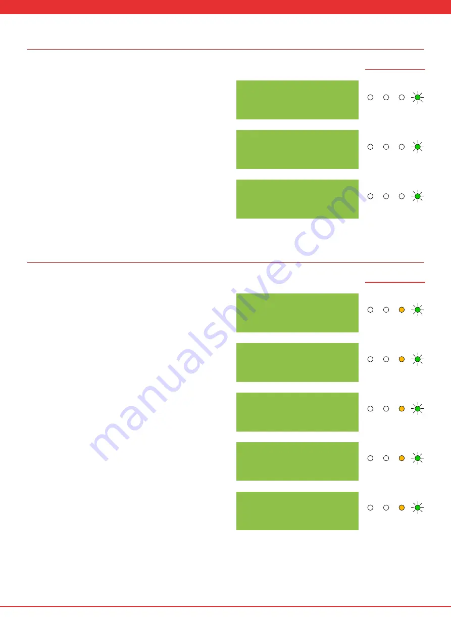
Normal Operation
Fault Conditions
18. The alarm log format is shown right. The most recent alarm is shown
first (1). Cycle through previous alarms by pressing SET. On the top line
the date and time of the alarm is shown (depending upon the current
time set in the control unit - see step 19). On the bottom line the average
sensor cable temperature at the time of the alarm is shown (in this case
33.4°C) and the lowest measure cable resistance during the time the
alarm occurred and the alarm was reset (in this case 65.2MΩ).
19. The last menu option shows the current time and date set in the
control unit. This can only be updated using the laptop software. Contact
your support partner to obtain the latest version of the software and
operating instructions. If the time and date is not set the starting value
when the control unit is first switched on is “00:00 00/00/18”.
20. If the SELECT or SET buttons have not been pressed for 10s the control
unit will return to normal operation and display the diagnostic screen.
21. If the control unit has been erased or not commissioned the screen
will show “FAULT: NO SETUP”. Press and hold the SET and SELECT buttons
for 15s to return to the start of the commissioning process (see step 1).
22. In the event the voltage to the ProReact EN Analogue Composite
Control Unit falls below the minimum value (see “Technical Specifications
- ProReact EN Analogue Composite Control unit”), the fault output will
stop conducting, the fault LED will light and the screen will show “FAULT:
UNDER V”.
23. If a fault occurs in the sensor cable, the fault LED will illuminate,
the fault output will stop conducting and the control unit will try to
determine which core has broken (if only one core has broken). The
screen will display as shown right. The letters correspond to the “S C C R”
connections on the PCB (see “Control Module Wiring”)
If “S x C R” is shown then this can indicated either a break on the
corresponding clear core or that the clear cores have been wired the
wrong way round (see “Typical System Wiring”).
If “S C C x” is shown this indicates that there is a possible break or poor
connection on the red core of the sensor cable, or the calculated cable
length does not match the actual cable length attached to the controller.
If “S x x x” is shown then this can indicate that the clear core adjacent to
the red core is broken or has a poor connection, more than one core on
the sensor cable is broken or the sensor cable has been disconnected.
1-10:18 05/03/18
33.4
O
C A: 65.2M
Ω
FAULT: NO SETUP
CURRENT 200M
Ω
13.4
O
C A: 88.6M
Ω
FAULT: S x C R
CHECK CABLE
FAULT: S C C x
CHECK CABLE
FAULT: S x x x
CHECK CABLE
CURRENT TIME
10/18 05/03/18
FAULT: UNDER V
LED Illustrations
LED Illustrations
Alarm Fault Power
Pre
Alarm
Alarm Fault Power
Pre
Alarm
Alarm Fault Power
Pre
Alarm
Alarm Fault Power
Pre
Alarm
Alarm Fault Power
Pre
Alarm
Alarm Fault Power
Pre
Alarm
Alarm Fault Power
Pre
Alarm
Alarm Fault Power
Pre
Alarm
Alarm Fault Power
Pre
Alarm
Alarm Fault Power
Pre
Alarm
Alarm Fault Power
Pre
Alarm
Alarm Fault Power
Pre
Alarm
Alarm Fault Power
Pre
Alarm
Alarm Fault Power
Pre
Alarm
Alarm Fault Power
Pre
Alarm
Alarm Fault Power
Pre
Alarm
Alarm Fault Power
Pre
Alarm
Alarm Fault Power
Pre
Alarm
Alarm Fault Power
Pre
Alarm
Alarm Fault Power
Pre
Alarm
Alarm Fault Power
Pre
Alarm
Alarm Fault Power
Pre
Alarm
Alarm Fault Power
Pre
Alarm
Alarm Fault Power
Pre
Alarm