background image

8

9.

PARTS REPLACEMENT

9.01 Heater Replacement

1.

Disconnect power.

2.

Remove the clamps securing the
thermostat bulbs to the floor. Carefully bend
the bulbs to a vertical position.

3.

Remove two screws securing control
panel and carefully lift control panel and
lay it on it's face.
Model 14EG: Then remove three screws
securing the front z-bracket,screws are
located directly above the control panel.
Remove one screw on back wall that
secures the oven floor. Lift bottom floor
straight up and out to remove it.
Model 25 & 45: Remove ten screws that
secure floor and lift out.

4.

Disconnect heater terminals and heater
mounting screws. Carefully lift straight
up and out.

5.

Replace with new heater, reinstall in
reverse order.

9.02 Probe Replacement, Models 25 & 45

1.

Disconnect power.

2.

Remove back panel screws.

3.

Pull probe straight out.

4.

Open control panel by removing top
screws
which secure it and disconnect probe
terminals.

5.

Replace with new probe, reinstall in
reverse order.

9.03 Motor Replacement (Mechanical

Models only)

1.

Disconnect power.

2.

Open control panel by removing top
screws which secure it and disconnect
motor and heater terminals.

3.

Remove screws which secure lower
floor and lift out.

4.

Disconnect/remove heater mounting
screws, remove heater and wires.

5.

Detach blower wheel from motor shaft.

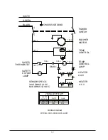
8.04 Heater Resistance Check

WARNING

DISCONNECT OVEN FROM ITS POWER
SOURCE BEFORE PROCEEDING.  REFER
TO THE APPROPRIATE WIRING DIAGRAM
AT THE END OF THE MANUAL AND
LOCATE THE ELECTRICAL LEADS FOR
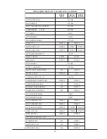
THE HEATER. USE THE VALUES IN THE
HEATER COLD RESISTANCE TABLE TO
FIND THE APPROPRIATE VALUE. BE SURE
TO DISCONNECT AT LEAST ONE HEATER
LEAD FROM THE TERMINAL STRIP
BEFORE TAKING THE RATING WITH YOUR
OHM METER. AGAIN, IT IS IMPERATIVE
THAT THE UNIT BE COMPLETELY
DISCONNECTED FROM ITS ELECTRICAL
POWER SOURCE BEFORE ANY
READINGS ARE TAKEN.

If the heater is open (infinite resistance) it should
be replaced.  If the heater reads less than five
ohms it is shorted and should be replaced.
Check the resistance between each lead of the
heater and a base metal point on the oven
chassis.  If there is less than infinite resistance
(a million ohms or greater) between the heater
and chassis, the heater is shorted to the ground
and should be replaced.  Also, inspect all wires
leading to the heater for signs of shorting or
electrical contact to chassis of oven.

Summary of Contents for 14EG

Page 1: ...s 14EG 6520 6521 25EG 6522 6523 45EG 6524 6525 25EM 6526 6527 45EM 6528 6529 Thermo Electron Corporation Millcreek Road Box 649 Marietta Ohio 45750 USA Phone 740 373 4763 Toll Free 800 848 3080 FAX 740 373 4189 ManualP N3177886 Rev E Dated 11AUG05 ...

Page 2: ...N CORPORATION MAKES NO REPRESENTATIONS OR WARRANTIES WITH RESPECT TO THIS MANUAL IN NO EVENT SHALL THERMO BE LIABLEFORANYDAMAGES DIRECTORINCIDENTAL ARISINGOUTOFORRELATEDTO THE USE OF THIS MANUAL For repair information or replacement parts assistance from the manufacturer call Technical Services using our toll free telephone number 888 213 1790 FAX 740 373 4189 ...

Page 3: ...ES REVISION STATUS 6 99 B 11 01 6 Add plastics can melt note C 11 02 2 5 7 8 11 High limit cutout for models 25 45 replacedbyhydraulicthermostat ECO 020809A D E 9 04 8 05 12 13 36100121 Correctedsafetythermostatcallout newmanual manufacturelocation ...

Page 4: ...ING AND DAMAGE 1 3 GENERAL INFORMATION 2 4 SPECIFICATIONS 3 5 INSTALLATION 4 6 EXPLANATION OF CONTROLS 4 7 OPERATION 5 8 MAINTENANCE SERVICING 7 9 PARTS REPLACEMENT 8 10 ELECTRICAL DRAWINGS 11 11 REPLACEMENT PARTS LIST 13 12 WARRANTY 14 ...

Page 5: ...AL SAFETY THIS APPARATUS MUST BE PROPERLY GROUNDED BE SURE THAT THE POWER SUPPLY IS OF THE SAME VOLTAGE AS SPECIFIED ON THE NAMEPLATE DANGEROUSVOLTAGESEXISTWITHINTHISUNIT SERVICESHOULDBEPERFORMED ONLY BY QUALIFIED PERSONNEL DISCONNECT THE UNIT FROM ITS ELECTRICAL SOURCE REMOVE THE SHELVES AND THERMOMETER IF INSTALLED DISCONNECTING ANY COMPONENT FROM THE CIRCUIT WITHOUT PRIOR REMOVAL OF THE POWER S...

Page 6: ...handise was carefully packed and thoroughly inspected beforeleavingourfactory 2 02 Responsibility for safe delivery was assumedbythecarrieruponacceptanceofthe shipment therefore claimsforlossordamage sustained in transit must be made upon the carrier by the recipient as follows 1 VisibleLossorDamage Noteanyexternal evidence of loss or damage on the freight bill or express receipt and have it signe...

Page 7: ......

Page 8: ...onvection ovens are ideal fordryingpowders soilsamples papergoods semiconductors and cosmetics 3 03 Models25EMand45EMusemechanical convection as a method of heat transfer Mechanical convection can be defined as a positiveandplanneddirectionalairfloworforced air circulation within the chamber 3 03 1 Air is drawn into the chamber through venttubeslocatedinthebottomoftheovenand is heated as it passes...

Page 9: ......

Page 10: ...18 in 390 x 455 mm 21 5 x 24 x 40 in 550 x 610 x 1020 mm Net Weight 69 lbs 31 kg 93 lbs 42 4 kg 103 lbs 46 7 kg 120 lbs 54 4 kg 130 lbs 59 kg Chamber Volume 1 4 cu ft 39 liters 2 5 cu ft 71 5 liters 2 5 cu ft 71 5 liters 4 5 cu ft 129 liters 4 5 cu ft 129 liters Shelves Supplied Maximum 2 6 2 6 2 6 2 10 2 10 Electrical Data all models 50 60 Hz 115V 230V 0 8 kW 7 1 A 0 8 kW 3 5 A 1 3 kW 11 3 A 1 3 ...

Page 11: ......

Page 12: ...SE A TWO PRONG ADAPTER PLUG 5 03 Determine the total amount of current beingusedbyotherapparatusconnectedtothe circuit that will be used for this apparatus It is critical that the added current demand see nameplate ofthisandotherequipmentusedon the same circuit does not exceed the rating of the fuse or circuit breaker CAUTION BE SURE THAT THE POWER SUPPLY IS OF THE SAME VOLTAGE AS SPECIFIED ON THE...

Page 13: ...ecaptoamoreclosedpositiontoretain heat Insert shelf supports into the holes punched in the side walls of the inner chamber Insert the shelvesintotheshelfsupportsandtrytokeepan equal distance between shelves whenever possible Never cover the shelves with foil or reduce their open surface area by more than 75 this will greatly reduce convection and henceuniformityandcontrolwillsuffer A thermometer i...

Page 14: ...rcirculation general loading procedures are applicable to bothtypesandmustbefollowed Itisimportant for uniformity and recovery that air circulation within the chamber is not restricted 1 At least one 1 inch 2 5 cm should be left between objects placed on the shelves NOTE WITHIN THE MECHANICAL CONVECTION CABINETS OBJECTS SHOULD NOT BE PLACED ON THE SHELVES IN SUCH A MANNER TO BLOCK THE MOVEMENT OF ...

Page 15: ......

Page 16: ...operating temperatures The mass of the load can also affect stabilization time 4 Makecertainseverelinevoltagefluctuations arenotoccurring 5 Makecertainallwireconnectionsaresecure attheirterminals 6 Make certain that an intermittent failure of the switch thermostat or wiring has not occurred Isolatethecause repairorreplace 8 03 Heat Loss Inspectdoorgaskettomakecertainitfitsfirmly against cabinet at...

Page 17: ......

Page 18: ...op screws which secure it and disconnect motorandheaterterminals 3 Remove screws which secure lower floor and lift out 4 Disconnect remove heater mounting screws remove heater and wires 5 Detach blower wheel from motor shaft 8 04 Heater Resistance Check WARNING DISCONNECT OVEN FROM ITS POWER SOURCE BEFORE PROCEEDING REFER TO THE APPROPRIATE WIRING DIAGRAM AT THE END OF THE MANUAL AND LOCATE THE EL...

Page 19: ...t screws on each knob 14 EG only 6 Tag lead wires and detach from thermostats 7 Model14EG Removescrewssecuring thermostat to control panel Remove two screws securing angle cover lo cated inside of inner chamber on the front left side This will give you room to pullthermostatbulbsout Model 25 45 Remove thermostat bracketfromcontrolpanel Removether mostatfrombracket Removeknobfrom thermostat 8 Pullt...

Page 20: ...ecure door handleandreplacehandle 3 Reassemble in reverse order 9 07 Door Latch Grabber on body of unit 1 Disconnectpower 2 Removescrewswhichsecuredoorlatch grabber and remove them from front NOTE Usedretainingnutswillfall intoovenbody 3 Insert replacement latch assembly throughopenslotandfastenwithscrews and washers provided ...

Page 21: ...TCH CONNECTIONS WIRING DIAGRAM MODEL 14 EG LI 1 N 2 3 LI 2 N 3 HIGH SAFETY TN TN TN THERMOSTAT CONTROL TEMPERATURE SAFETY BK GR WH YL RD BK WH OR L1 N BK RD 3 2 1 LINE CORD ASS Y 3 HEAT SWITCH LEAD ASSY LIGHT ASSY 2 PLACES LEAD ASSY THERMOSTAT 2 PLACES HEATER LEAD ASSY 3 PLACES ...

Page 22: ... V HEATER 318K OHMS 0 C 6 6K OHMS 100 C 1600 1100 HEATER 32 5 47 HEATER COLD RESISTANCE BETWEEN TB1 4 AND TB1 2 34247440 34247439 PART NO WATTS TB1 2 TB1 2 TB1 1 TB1 1 TB1 4 TB1 3 TB1 2 TB1 1 EMR CHASSIS GROUND GREEN 230 V SAFETY CUTOUT LAMP TEMP CONTROL LAMP EMR 1 WHITE BLACK 2 1 5 4 SAFETY THERMOSTAT OHMS ...

Page 23: ... 3 T A T S O M R E H T Y T E F A S 4 3 2 5 7 1 3 D E T H G I L N O N T S P D H C T I W S A N 8 1 3 5 7 1 3 T A E H 3 H C T I W S 9 6 2 5 7 1 3 A N 8 1 6 1 5 T O O F G N I L E V E L 6 3 3 5 7 1 3 R E L L O R T N O C E R U T A R E P M E T 4 3 2 5 7 1 3 0 3 7 6 7 1 3 R O S N E S E R U T A R E P M E T A N 5 3 7 6 7 1 3 S S E N R A H N E V O Y M O N O C E A N 7 2 7 6 7 1 3 N O I T I S O P 6 K C O L B M...

Page 24: ...l warranty period The Technical Services Department must give prior approval for return of any components or equipment At Thermo s option all non conforming parts must be returned to Thermo Electron Corporation postage paid and replacement parts are shipped FOB destination THIS WARRANTY IS EXCLUSIVE AND IN LIEU OF ALL OTHER WARRANTIES WHETHER WRITTEN ORAL OR IMPLIED NO WARRANTIES OF MERCHANTABILIT...

Page 25: ......

Reviews: