background image

4.3.2.1. 

Steel Cord Installation: mechanical mounting  


WARNING


The correct installation of the steel cord, according to the directions set out below,"


La corretta installazione della fune, in accordo con le indicazioni specificate di 
seguito, is a primary condition to ensure the proper functioning of the 
protection device.


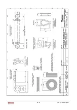
The installation of the steel rope is by using a set of accessories described and listed 
below :


• 

Safety Spring (1)

: installed at the ends, are used to maintain tension in the steel rope, 

in


step d 'installation must be properly tensioned, to ensure that in case of breakage, 

the switch is pressed by the spring installed on the opposite side.  


• 

Redance (2)

: installed near the springs of security needed to create the terminal loop of


the rope, and allows the fixing of the rope by the steel cord clampe.  


• 

Steel  Cord  Clamp  (3)

:  installed  after  the  redance  allow  you  to  set  the  end  of  the 

rope


made up the ring back.  


• 

Helicoidal Nut (4)

: installed on the fixed points has the function to end support, 

installed


at intervals of max. 3 mt. along the rope, serves to support the rope to avoid 

that the same goes slack.  


• 

Red  Steel  Cord  (5)

:  The  steel  cord  is  flexible  plastic,  which  is  the  element  to  operate 

the


lever switch.  


Fig. 4-3-2-1


Referring to the drawing figure 4-3-3, install the device and its accessories as described:


14 / 30


Cod.: PL-000603X-D002G


Summary of Contents for PRO-LINE 60-30G

Page 1: ... Italia S r l PROTECTION DEVICE Series PRO LINE Operating and Service Manual The manual includes ATEX safety informations for applications in potentially esplosive atmospheres classified as Zone 22 PL 000603X D002G ...

Page 2: ... D Cattaneo D Molteni Revised Steel Cord Connection 14 10 2014 G D Cattaneo D Molteni Revised Operating Temperature 10 06 2011 F R Cavenago D Molteni Revised Technical Data Table 15 06 2010 E D Molteni GTO Upgrading Complete 10 02 2009 D D Cattaneo D Molteni Upgrading ATEX Section 04 11 2003 A D Molteni P Danelli Emission DATE REV DRAWN UP APPROVED DESCRIPTION 2 30 Cod PL 000603X D002G ...

Page 3: ... Unpacking 11 4 3 Positioning and Installation 12 4 3 1 Belt Run Off Switch Mod 60 30G 12 4 3 2 Rope Emergency Switch Mod 60 31G 13 4 3 2 1 Steel Cord Installation mechanical mounting 14 4 3 3 Limit Switch Mod 60 32G 18 4 4 Electrical Wirings 18 4 5 ATEX Safety Informations for use in Explosive Atmospheres 19 5 USE OF PRODUCTS 21 5 1 General 21 5 2 Uses not permitted 21 6 MAINTENANCE 22 6 1 Warran...

Page 4: ... a general index that allows rapid positionning of the subject of interest The indications more important are highlighted in bold type and preceded by symbols illustrated and defined below DANGER Possible dangers and important requirements for the protection of operators safety non compliance or observation may involve risks to the safety of the operators and or demages goods and things WARNING Re...

Page 5: ...art of this documentation and contains all the information needed to ensure the efficient operation of the unit with particular regard to personnel safety The following standards have been referred to in the design of the unit 2006 42 CE MACHINE SAFETY DIRECTIVE 2014 35 CE LOW VOLTAGE LVD DIRECTIVE 2004 108 CE EMC DIRECTIVE STANDARDS IEC 60529 A1 A2 2013 EN 60947 5 1 2005 EN 60947 5 5 1998 A1 2006...

Page 6: ...safety devices for correct operation of the device 2 3 Safety in Maintenance Before carrying out any maintenance operation on the products it is mandatory Read this instruction manual Use the correct tools for the maintenance operations that have to be done Do not clean the electrical parts of the feeder with water or other fluid On completing the repair work check that all the tools have been col...

Page 7: ...fixed to certified units fig 2 4 To understand the markings see drawing TG 0PL603X E001D attached to chapter 8 DANGER For applications in explosion hazardous areas classified ATEX Zone 22 must be strictly followed the instructions given in paragraphs 4 5 and 6 3 WARNING THERMO RAMSEY will not be held liable for applications in explosion risk areas that do not conform to the specifications in the a...

Page 8: ...r RAL 3020 Impact Resistance 50g 11ms Vibrations withstanding 10g 10 to 500Hz according to IEC 60068 2 27 Microswitches Between open contacts in a given circuit 1500V Electrical Rigidity Between contacts connected together and exposed conductive parts 2000v Microswitches Impulse withstand voltage U imp 4KW Rated Insulation Voltage Insulation voltage Ui 400V Ui 400V IEC EN 6947 1 Microswitches Ithe...

Page 9: ...ing condition is not in contact with the belt and thus keeps its vertical position When the belt runs off it touches the roller tilts it and thus operates the inside microswitches Fig 3 3 1 The position of the external lever on the shaft may be changed as required thus allowing the mounting of the housing on an horizontal vertical or any inclined plate but never inverted The roller is sized for a ...

Page 10: ...croswitches operate at a 18 2 inclination of the external lever Each microswitch is provide of N 1 NC contact N 1 NO contact This devices is used for the safety of the operators on belt conveyors 3 5 Limit Switch Mod 60 32G It consists of a external lever equipped with one contact wheel to be operate by the controlled machine Fig 3 5 1 The position of external lever on the shaft may be changed as ...

Page 11: ...r damage to persons or property Upon receipt of the device make sure that this has not been damaged during transport and that the packaging is intact and has not been tampered with If damage is detected by the transport needs to be taken within 7 days of receipt of goods the steps needed to cover the damage under the provisions of supply contract INFORMATIONS In the case of storage waiting for the...

Page 12: ...n Off Switch Mod 60 30G The Belt Run off Switch is normally installed on both sides of the belt near the drum head and tail For belts of particular extension there should be of flags even along the ribbon each 200 meters about and immediately after the loading points The unit must be installed at a distance from the belt such that the roller lever is angled 30 degrees when the belt is in the posit...

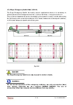
Page 13: ...both sides along the entire tape with a maximum distance of 50 meters between two subsequent switches or 25 meters between a switch and a fixed point Fig 4 3 2 DANGER The Rope Emergency Switch can only be used in control circuits WARNING For the correct operation of the emergency switches use only accessories steel cord springs helicoidal nut etc original THERMO RAMSEY The use of accessories other...

Page 14: ... case of breakage the switch is pressed by the spring installed on the opposite side Redance 2 installed near the springs of security needed to create the terminal loop of the rope and allows the fixing of the rope by the steel cord clampe Steel Cord Clamp 3 installed after the redance allow you to set the end of the rope made up the ring back Helicoidal Nut 4 installed on the fixed points has the...

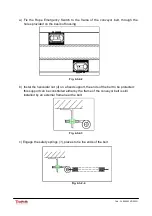
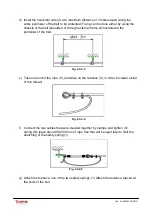
Page 15: ... b Instal the helicoidal nut 4 on a fixed support the ends of the belt to be protected this support can be constituted either by the frame of the conveyor belt is still installed by an external frame near the belt Fig 4 3 2 3 c Engage the safety springs 1 places to tie the ends of the belt Fig 4 3 2 4 15 30 Cod PL 000603X D002G ...

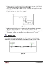
Page 16: ...belt Fig 4 3 2 5 e Take one end of the rope 5 and wrap on the redance 2 in order to create a kind of thin thread Fig 4 3 2 6 f Connect the two cables that were created together by clamps and tighten 3 during this leave about 280 300 mm of rope free that will be used later to limit the stretching of the safety spring 1 Fig 4 3 2 5 g Attach the redance one of the two safety springs 1 Attach the reda...

Page 17: ... properly tensioned and visible and limit the elongation of the spring as shown in figure 4 3 2 5 to a maximum length of 180 mm l l If the switch is placed in central position to the perimeter to be protected repeat all the steps indicated from the point e for the second half of the perimeter INFORMATIONS For installations with ropes lengths greater than 10 15 meters in order to facilitate the ope...

Page 18: ...ts that allow an extension of up to 200 mm approximately 12 kg Strictly follow the installation instructions as by lengthening the upper are no longer guaranteed the characteristics of elasticity and then operating the device The length of the rope should not be above 25 meters per stroke 4 3 3 Limit Switch Mod 60 32G The Limit Switch must be positioned properly in order to detect any movement hor...

Page 19: ...ble glands are locked firmly on the housing In accordance with current legislation the housing must be grounded through ground wire to appropriate section 4 5 ATEX Safety informations for use in Explosive Atmospheres European directives ATEX 2014 34 UE for equipment and 1999 92 CE for the workplace plant establishing the essential safety requirements against the risk of explosion in hazardous area...

Page 20: ...core cables It must be ensured the connection of equipotential by loosening and rotation devices at the connections provided both inside and outside of the devices The location of the devices must be chosen taking into account the accessibility for maintenance and cleaning The devices must be protected from external influences eg mechanical efforts and or thermal which can be submitted and these a...

Page 21: ... lines packaging etc The main areas of use are material extraction industries and manufacturing industries 5 2 Uses not permitted The product should only be used for the purposes intended by the project as per the instructions given in paragraphs 3 3 3 4 and 3 5 for any purpose other than refer to the company Thermo Ramsey Italian S r l 21 30 Cod PL 000603X D002G ...

Page 22: ... due to a bad inappropriate or negligent use of the product as well as inexperience and careless handling and or maintenance of the product 6 2 Maintenance indications In general the product does not require special maintenance yet it recommends a periodic functional check as indicated below Remains the sole responsibility of the user to determine the frequency of controls over time characterized ...

Page 23: ... of electrical installations in hazardous areas with explosion IEC 60079 17 WARNING To verify every 6 months integrity of the gasket of the cover and if is necessary to replace it WARNING Check monthly the connection of the ground conductor WARNING Check monthly the operation of the operating arm ensuring with repeated moviments in both directions that the movement is free and that not block marks...

Page 24: ...mperature in which the device will be stored is in accordance with the specifications in the technical data table 7 2 Dismantling the unit The dismantling activities is the decommissioning and disposal of the device in the order shown below Disconnect the device from the circuit The waste products waste produced by this activity must be disposed of in accordance with the laws of the country in whi...

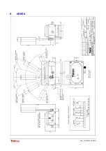
Page 25: ...8 ANNEX 25 30 Cod PL 000603X D002G ...

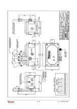
Page 26: ...26 30 Cod PL 000603X D002G ...

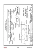
Page 27: ...27 30 Cod PL 000603X D002G ...

Page 28: ...28 30 Cod PL 000603X D002G ...

Page 29: ...29 30 Cod PL 000603X D002G ...

Page 30: ...30 30 Cod PL 000603X D002G ...

Reviews: