background image


19


A  liquid  sub-cooling  of  about  10oF  leaving  the  condenser  is  good  over  a  wide  range  of  operating 
conditions for a system with a TXV in the evaporator like the AH2436A/BE1 & AH4260A/BE1. 


MEASURING TEMPERATURE DROP ACROSS THE “A” COIL: 
 

The temperature drop across the coil should be around 18oF to 23oF difference between inlet and outlet 
air. This should be measured as close to the air handler as possible, to eliminate duct losses. 
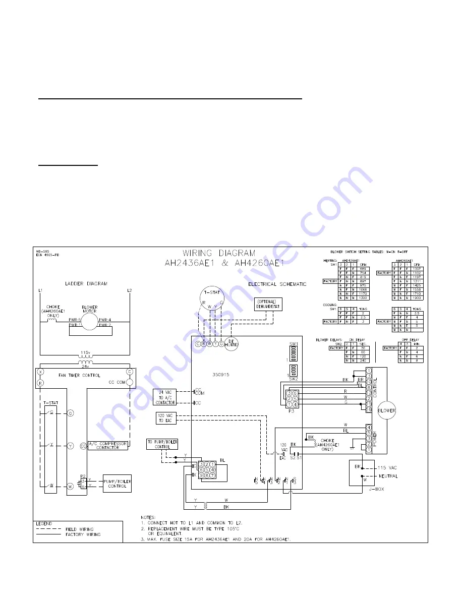


ELECTRICAL 

 
All  wiring  must  conform  to  the  provisions  of  local  codes  or  in  the  absence  of  local  codes  with  the 
provisions of the National Electrical Code, ANSI/NFPA No. 70-Latest Edition and this instruction manual. 
Equivalent type wire must be used if any of the original wire supplied with the unit needs to be replaced. 
 

NOTE:

 Condensing unit is not included in above amp rating. 


Summary of Contents for AH2436AE1

Page 1: ...SE INSTRUCTIONS MUST BE LEFT WITH THE USER AND SHOULD BE RETAINED FOR FUTURE REFERENCE BY QUALIFIED SERVICE PERSONNEL Improper installation adjustment alteration service or maintenance can cause injury or property damage Refer to this manual For assistance or additional information consult a qualified installer service agency or manufacturer listed below THERMO PRODUCTS LLC BOX 237 DENTON NC 27239...

Page 2: ......

Page 3: ... HOT WATER COIL 8 BLOWER AIR ADJUSTMENT 9 DUCT SYSTEM 13 DUCT SIZING CHART 14 INDOOR EVAPORATOR COIL 14 TUBING LINE SETS 14 HOW TO MEASURE LIQUID SUB COOLING 18 MEASURING TEMPERATURE DROP ACROSS THE A COIL 19 ELECTRICAL 19 UA ADAPTER CABINET 22 RECOMMENDED SUSPENSION PROCEDURE FOR AH AIR HANDLER 22 ECM TROUBLE SHOOTING 23 TROUBLE SHOOTING CHARTS 26 SEQUENCE OF OPERATION 28 REPLACEMENT PARTS LIST 2...

Page 4: ... is not to be used to condition during construction When testing electrical equipment always follow standard electrical procedures and precautions DO NOT wet electronic components during hydronic testing Wetting electronic components may damage circuitry and cause a hazardous situation Dry moisture from all leads and terminals if wetting occurs Wait at least 24 hours for the circuit to fully dry b...

Page 5: ... KNOCKDOWN OF AH2436 1 Start with unit setting in a vertical position Figure A 2 Remove blower access door 3 Remove screws from front a coil access panel front heating option access panel front middle panel and supply air end casing 4 Remove the front A coil drain pan retainer and the horizontal drain pan support shipping screw s from the right side casing 5 Remove the evaporator a coil assembly 6...

Page 6: ...AH2436 FROM LEFT TO RIGHT AIRFLOW TO RIGHT TO LEFT AIRFLOW The AH2436 is shipped ready for horizontal left to right airflow or vertical operation If horizontal right to left airflow is required follow these steps SEE FIGURE 1 FOR STEPS 1 THRU 6 1 Remove front panels from unit and pull the coil assembly from the housing 2 Remove the horizontal drain pan and re install it to the opposite side of the...

Page 7: ...ttom coil section Lift top off of bottom section 7 If the Air Handler needs to be completely knocked down follow steps in procedure for the knockdown of the AH2436 REASSEMBLY OF AH4260 To reassemble the air handler reverse steps above starting with number 7 SETTING UP THE A COIL FOR AIR CONDITIONING The AH2436 AH4260 come with the A coil pre installed for vertical and left to right horizontal airf...

Page 8: ...izontal drain pan assembly should rest against the left side casing insulation and the side support angle 7 Re install the front a coil drain pan retainer in front of the a coil drain pan For all orientations 8 Cut open the appropriate drain pan drain access hole in the front A coil access panel 9 Slip the Suction line grommet panel over the suction line up to the access panel surface Figure C 11 ...

Page 9: ...ng 3 Remove the A coil assembly Slide the horizontal drain pan assembly off of the right side of the A coil and discard 4 Remove A coil bottom front side rear supports side support drain pan angles and rear a coil drain pan retainer 5 Turn air handler over 6 Re install supports angles and retainer removed in step 4 in the counterflow configuration using pre punched holes located in the center of t...

Page 10: ...ng and rear coil module casing 5 Top blower section is now disengaged from bottom coil section 6 Lift blower module off of coil module 7 Turn blower module over 8 Remove return air end casing from coil module 9 Place coil module on top of inverted blower module 10 Re install return air end casing on top of coil module and secure with screws 11 Re install all screws which secure blower module to co...

Page 11: ...t out appropriate holes in insulation realign top door and secure into place 5 Make appropriate hydronic connections to inlet blower side and outlet duct side of coil and braze into place 6 Seal connections through panel with duct sealer or equivalent Figure F If drilling or screwing into panel or plate is necessary make certain drill does not penetrate into any part of evaporator coil or hot wate...

Page 12: ...e of the condensing unit that will be used 2 If Hydronic heat is to be used identify your BTU heat requirements preferred supply air temperature water temperature and water flow through the coil in gallons per minute 3 Locate the blower control board mounted to the front of the blower assembly 4 Locate the red switch block labeled SW1 for adjusting the Heating and Cooling blower speed 5 Locate SW2...

Page 13: ...ts the BTU and Supply Air temperature desired 4 Read the letter associated with that point and use it to find the switch settings in the table below the chart The table below the switch settings represent the actual numbers represented by the chart Table C1 COOLING SWITCH SETTINGS A C TONS CFM AH2436A BE1 COOL Settings SW1 AH4260A BE1 COOL Settings SW1 4 5 6 4 5 6 2 800 OFF OFF OFF 2 1 2 1000 ON O...

Page 14: ... 58615 60509 62490 64505 66717 Supply Air ºF 136º 133º 131º 128º 126º 124º 121º 118º Heat Kbtu H 50092 52795 55294 58057 60597 63317 66151 69343 Supply Air ºF 134º 132º 129º 127º 124º 122º 119º 116º Heat Kbtu H 49061 51611 53962 56554 58928 61461 64090 67039 Supply Air ºF 132º 130º 127º 125º 122º 120º 117º 114º Heat Kbtu H 47654 50011 52174 54547 56711 59009 61382 64031 Supply Air ºF 130º 127º 125...

Page 15: ...y Air o F 145 142 139 137 134 131 129 125 Heat Kbtu H 82 86 90 95 99 104 109 114 Supply Air o F 134 132 130 128 126 124 121 119 Heat Kbtu H 70 74 78 82 86 91 95 101 Supply Air o F 133 131 129 127 125 123 120 118 Heat Kbtu H 69 73 77 81 85 89 94 99 Supply Air o F 132 130 128 126 124 121 119 117 Heat Kbtu H 68 72 75 79 83 87 91 96 Supply Air o F 131 129 127 124 122 120 118 115 Heat Kbtu H 66 70 73 7...

Page 16: ...and Air Conditioning Engineers Inc ASHRAE Latest Edition Fundamentals Volume To aid you in evaluating existing duct systems quickly review the chart on Page 14 which shows the CFM capacity for square inch areas based on 10 wc static pressure SP loss on the supply systems Each of the system s components trunk lines take offs runs and register and grill free areas must be properly sized and matched ...

Page 17: ...IN PAN is attached to the bottom of the evaporator coil to collect water condensed out of the air Two drain fittings are provided for connection to a convenient drain point 3 HORIZONTAL CONDENSATE DRAIN PAN is attached to the right side of the first one for horizontal left to right air flow It may relocated to the left side as well A drain fitting is provided for connection to a convenient drain p...

Page 18: ... 1 2 HP14361A1 HP14421A1 HP1448xA1 HP1460xA1 7 8 3 8 1 1 8 1 2 1 1 8 5 8 AC14361E2 AC14421E2 AC1448xE2 AC1460xE2 7 8 1 2 1 1 8 1 2 1 1 8 5 8 NOTES For line lengths over 25 adjust charge accordingly per foot of variation from chart 65 oz per foot for 3 8 and 3 4 line set 674 oz per foot for 3 8 and 7 8 line set 694 oz per foot for 1 2 and 7 8 line set 72 oz per foot for 1 2 and 1 line set 76 oz per...

Page 19: ... the suction line are necessary if the outdoor condensing unit is level with the indoor evaporator coil or the indoor evaporator coil is 4 feet or less lower then the outdoor condensing unit Any horizontal runs of suction line should have minimum 1 2 pitch for every 10 feet of line towards the outdoor condensing unit See Figure I Figure I 2 A trap is necessary in the suction line at the indoor eva...

Page 20: ...r condensing unit The lines must be provided with sufficient protection and support to prevent damage when installed above ground When making on the job tubing a solder of 95 tin 5 antimony or any of the silver solders such as SilFos Phos Copper Easy Flo 35 or 45 should be used No attempt will be made here to instruct proper soldering or brazing technique but it is necessary that the installer be ...

Page 21: ...liquid line at the 3 00 o clock or 9 00 o clock position with the liquid line as the center of the clock Figure L Make sure the tube where the temperature is measured is not in direct sunlight Read the temperature at the liquid line Read the liquid pressure Then convert pressure into temperature Next subtract the measured tube temperature from the converted suction temperature The end result is th...

Page 22: ...fference between inlet and outlet air This should be measured as close to the air handler as possible to eliminate duct losses ELECTRICAL All wiring must conform to the provisions of local codes or in the absence of local codes with the provisions of the National Electrical Code ANSI NFPA No 70 Latest Edition and this instruction manual Equivalent type wire must be used if any of the original wire...

Page 23: ...EH212A 70A EH216A 85A The following points must be checked by the installer and or electrician before the air conditioning system is started 1 Check every electrical connection of PUSH ON or SCREW ON terminals to ensure it is on tightly on its proper post 2 Review wiring diagram for proper routing ...

Page 24: ...21 ...

Page 25: ...turn air opening can face either left or right by exchanging the front filter door and rear filter block off assemblies The AH AIR HANDLER is then placed on the UA adapter cabinet inlet side down The UA cabinet is equipped with a permanent washable air filter AH AIR HANDLER RECOMMENDED SUSPENSION PROCEDURE The detail below is the proper and safest way to suspend the AH These components should be e...

Page 26: ...eck power at motor Check low voltage 24 VAC R to C at motor Check low voltage connections G PWM W R C at motor Check for unseated pins in connectors on motor harness Test with a temporary jumper between R G Check motor for tight shaft Perform motor control replacement check Run Moisture Check Motor rocks but won t start Check for loose or compliant motor mount Make sure blower wheel is tight on sh...

Page 27: ... Check out motor controls wiring and connections thoroughly before replacing motor Automatically assume the motor is bad Orient connectors down so water can t get in Install drip loops Locate connectors above 7 and 4 o clock positions Use authorized motor and control model s for replacement Replace one motor or control model with another unless an authorized replacement Keep static pressure to a m...

Page 28: ...ssure for lowest noise Set low continuous fan CFM T stat in bad location 120V or 240V 120V or 240V Figure N ECM PIN CONNECTORS Troubleshooting table above and Figure N adapted from GE Industrial Systems publication GED 7161C Troubleshooting GE ECM Driven Systems ...

Page 29: ... AND MOTOR STILL DOES NOT RUN REPLACE MOTOR THIS GUIDE SHOULD BE USED IN THE CASE OF A STOPPED OR MANFUNCTIONED ECM BLOWER MOTOR THE FOLLOWING SHOULD HELP ESTABLISH THE TYPE OF MALFUNCTION OR DEVIATION FROM THE NORMAL BLOWER OPERATION TO USE THIS DIAGRAM YOU JUST NEED TO FOLLOW THE INSTRUCTIONS IN THE BOXES CHECK 24VAC SUPPLY TO INTEGRATED CONTROL IS THERE 24VAC ACROSS R B C ON THE INTEGRATED CONT...

Page 30: ...R HEAT 3 Status LED Flashes 1 COOL mode On 2 Blower On Delay Started 3 Condenser On 4 Status LED On continuous 1 FAN mode On 2 BLOWER LOW 3 Status LED On continuous G Active Y Active LIMIT Active FAN Mode On G Active W Active 1 HEAT mode On 2 Blower On Delay Started 3 Burner On 4 Status LED On continuous Yes Yes Yes Yes Yes Yes No No No No No No Yes No 1 BURNER Off 2 HEAT mode Off 3 BLOWER Off Del...

Page 31: ...E1 only In an emergency situation a defective ECM motor can be replace with a PSC motor to provide temporary circulating air flow for heating or cooling This is done by replacing the ECM motor in the motor mounting bracket with a PSC motor of similar Horsepower Wire the common lead typically white of the replacement PSC motor to the neutral common terminal on the fan control board N 1 through 7 Co...

Page 32: ...29 REPLACEMENT PARTS ...

Page 33: ...30 ...

Reviews: