Disassembly and Reassembly
57
6. Use a micrometer to measure the rod journals.
If the outside diameter of a rod journal is less
than 1.3742 in. (34.9047 mm), replace the
crankshaft or have a competent machine shop
grind the crankshaft to use undersize bearings.
7. Remove the plugs and the metering jet from
the oil passageways. Clean the passageways
thoroughly.
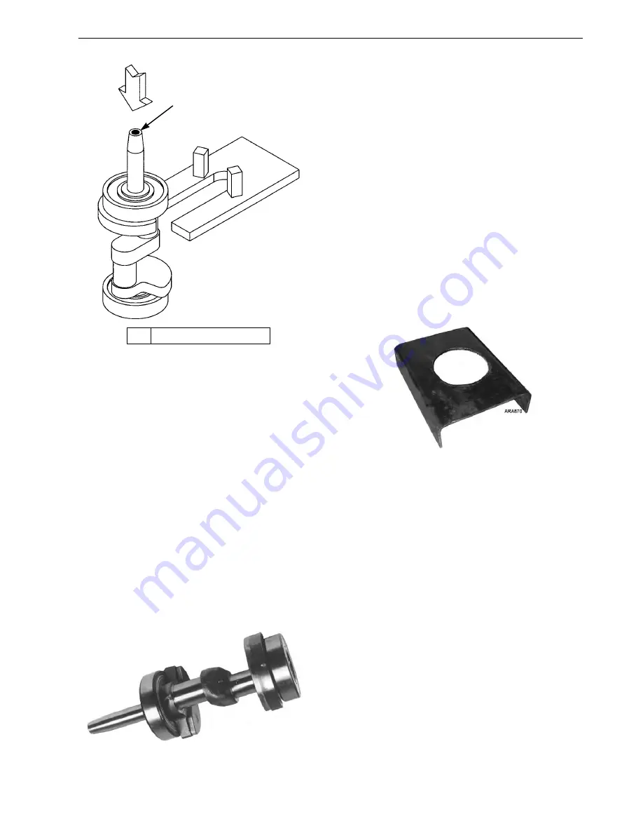
8. Reinstall all the plugs and the front seal
metering jet. Torque to 60 in-lb (6.8 N•m).
9. Install the oil pump drive pin in the rear main
journal before installing the ball bearings.
10. Press the ball bearings onto the crankshaft.
Press on the inner race of the bearing and
support the crankshaft under main journal
while performing this operation.
Figure 91: Install Bearings
Installation
1. Inspect the crankshaft to be certain it is
completely assembled before installing it.
Make sure that the plugs and the metering jet
(if used) are installed in the oil passageways,
and that oil pump drive pin and the bearings
have been installed. See steps 8, 9, and 10
above.
2. Position the compressor body with the seal
end down and support it to allow clearance for
the drive end of the crankshaft.
NOTE: Figure 92 on page 57 shows a
compressor support fabricated from 1/4 in. (6
mm) sheet metal. It is 10 in. (250 mm) wide,
13 in. (330 mm) long, and 4 in. (100 mm)
high. The hole has a diameter of 6 in. (150
mm).
Figure 92: Compressor Support
3. Use an oxy-acetylene torch with a large
rosebud tip to carefully and uniformly heat the
compressor body in the area around the seal
end bearing and monitor the temperature with
a noncontact thermometer P/N 204-1059 (or
similar). Ensure the heat is applied and the
required temperature established in the areas
with thicker material at the sides and top of
the bearing bore location, shown as item “1”
in Figure 94. Heat the area around the seal end
bearing to approximately 250 F (121 C). Do
not heat the area around seal end bearing
above 350 F (177 C).
1.
DO NOT
Use Spindle
Figure 90: Pressing Bearing Off Drive End
1
AGA774
AGA572


