8600 Series _______________________________________________________________________________Factory Options
6 - 1
Section 6 - Factory Installed Options
6.1 BUS - Back Up System (195875, 195877)
Before installation of BUS components, make sure the power
to the freezer is disconnected, the battery switch is turned off
and the freezer has warmed to ambient temperature.
The built-in BUS (back up system) will keep the freezer
chamber temperature below the critical level in the event of a
power or equipment failure. If power to the freezer fails, or tem-
perature increases to the back up alarm set point, the BUS
injects liquefied gas into the chamber to keep the chamber tem-
perature within the specified range.
The BUS operates on an internal 12-volt, rechargeable bat-
tery which is kept charged during normal operation by the inte-
gral battery charger.
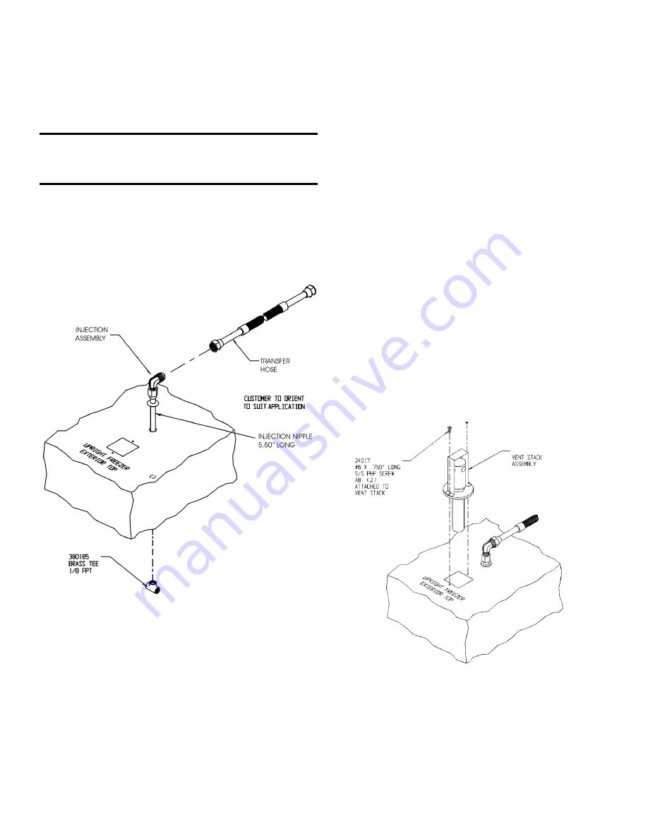
a. Installing the vent stack, solenoid and injection
assembly
1. Install the injection assembly through the 1/2” pre-
punched hole, directly behind the 2” vent stack hole in
the center of the chamber ceiling.
Note:
Cover the open end of injection assembly with tape to
keep insulation from entering the nipple.
2. Slide 3/8” flatwasher over open end of nipple.
3. Insert the covered end of the injection assembly through
the exterior hole.
4. Remove the tape covering from the end of the nipple and
install the 1/8” NPT brass tee on the open end of the nip-
ple. Place permagum sealant between the brass tee and
the interior top.
5. Remove the two Phillips head screws securing the metal
bracket on the vent stack assembly.
6. Install the vent stack through the opening and secure it to
the top of the freezer, using screws.
7. Go to the interior and seal around the end of the vent
stack with permagum.
Figure 6-1
Figure 6-2


