


4
-Explanation of Auxiliary Panel-
On the left side of the incubator control panel there
is an auxiliary panel which has the items shown in
the figure below. They are described as follows:
1) FUSE - This fuse is in line with the main power
cord that comes into the incubator. The rating of
this fuse is printed above the fuse holder. The
physical size of this fuse is 5 MM x 20 MM.
2) ALARM RELAY - This Alarm Relay output is
provided to the user for the purpose of remotely
monitoring the incubator in case of a high or low
temperature alarm condition. This alarm relay will
operate just as the audible alarm would. The
contact itself is an isolated form C (normally open/
normally closed) dry contact. This contact is to be
used for low voltage class 2 connections only. The
contact rating is 24 volts, 1.25 amps resistive.
Typical usages of the output are shown below.
In this configuration, the light will illuminate
whenever the unit goes into an alarm
condition...High or Low.
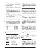
Temperatu
(Degree C)
Recorder
Output
(Millivolts)
-10
100
0
200
10
300
20
400
30
500
40
600
50
700
In this configuration, the light will go off in a high or
low temperature alarm condition.
NOTE
WIRING MUST CONFORM TO ALL LOCAL
ELECTRICAL CODES.
3) RS-232 OUTPUT (Optional Kit P/N 51200906) -
This output is used for two way communications
between the incubator and a personal computer.
With the use of communications/modem software
program, the user can record the temperature of
the incubator at their selected time periods and
store it in a file for use with a spreadsheet program.
The user can also change the setpoint temperature
from their personal computer and periodically
monitor the actual temperature, setpoint
temperature, and alarm status.
4) RECORDER OUTPUT - This is a DC millivolt
output which represents the temperature of the
incubator. The recommended main use of this is
with a chart recorder having an input impedance
of at least 1 megohm. The scaled temperature
output change is 10 millivolt/degree C. When the
incubator is operating at a negative temperature,
the chart recorder output is still positive. Use the
chart below to relate temperature to output voltage.
VOLTAGE SOURCE
VOLTAGE SOURCE


