


Rev 1.4 09/13/16
10
SPECIFICATIONS
Technology:
CMOS - Ceramic Metal Oxide
Semiconductor
Oxygen - Electro Chemical
Electrical Supply: 115-230 VAC, 50-60Hz
Output Signal:
Std. 4 x 8A Dry Contact Relays
(either NO or NC)
Opt. 4 x 0 - 5 VDC Analog
Alarm Outputs:
Three Level Contact Closure
Readout:
Digital Meter, Displayed in PPM
Gas Type, Range and options.
Accuracy:
10% Full Scale (CMOS)
1% Electrochemical (Oxygen)
Ranges:
0 - 1000 ppm CFC, HCFC, HFC
0 - 300 ppm NH
3,
, HCFC (Opt)
0 - 20% LFL Flammability
0 - 25% Oxygen
Response Time:
< 1 Minute per sample point
Operating Conditions:
CMOS Sensor -20
o
F to +120
o
F Non-condensing
Oxygen Sensor +40
o
F to +110
o
F Non-condensing
Controller
0
o
F to +120
o
F Non-condensing
Fault Diagnostics: Indicator Light or Readout for
Malfunction which include:
(See Figure 5)
Materials:
Controller
Polystyrene, NEMA 12/13, IP65
Design
CMOS Sensor PVC and porous PP
Weight:
Controller:
4 lbs. (Add 2 lbs. optional battery)
Dimensions:
Controller
10-1/2” W x 7-1/8” H x 4-1/4”D
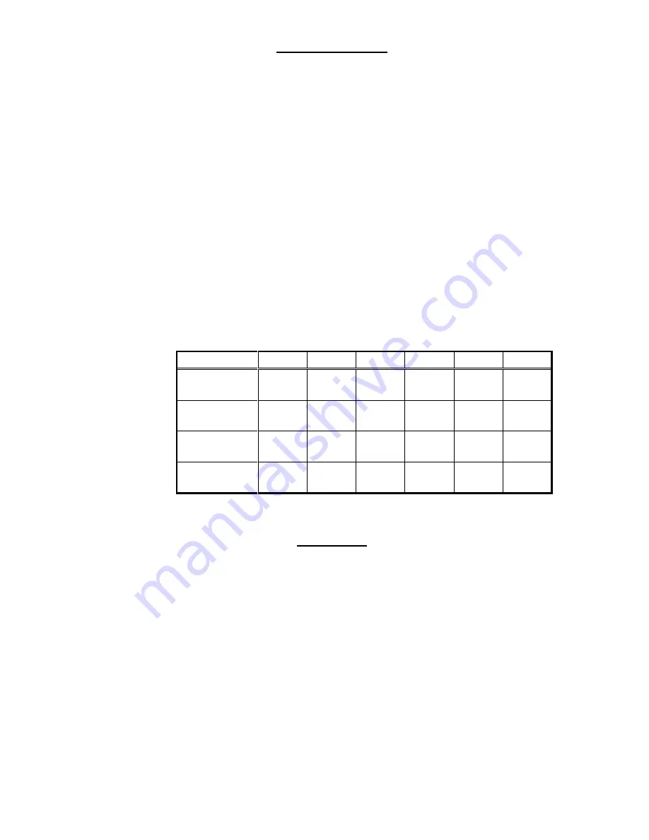
Initial factory settings are:
Channel
1
2
3
4
5
6
Gas
Sensor
Type
Full Scale
PPM
TWA Alarm
Level
Figure 10 - Initial Factory Settings
GLOSSARY
1.
PEL-
Permissible Exposure Limits - The employee’s average short term exposure in any 8-
hr work shift, which shall not be exceeded.
2.
CONTROLLER -
Processor mounted on wall which includes LCD Display, LED Alarms
Relays, and other functions
3
CEIL-
The concentration that shall not be exceeded during any part of the work day
.
4.
SPAN -
A full-scale reading on the LCD display.
5.
TLV-TWA -
The time -weighted average concentration for a normal 8 hr. work day and a
40 hr. work week, to which nearly all workers may be repeatedly exposed, day after day,
without adverse effect.
6..
ZERO -
An indication on the display indicating the presence or non-presence of CFC’s,
HCFC’s or HFC’s.