background image

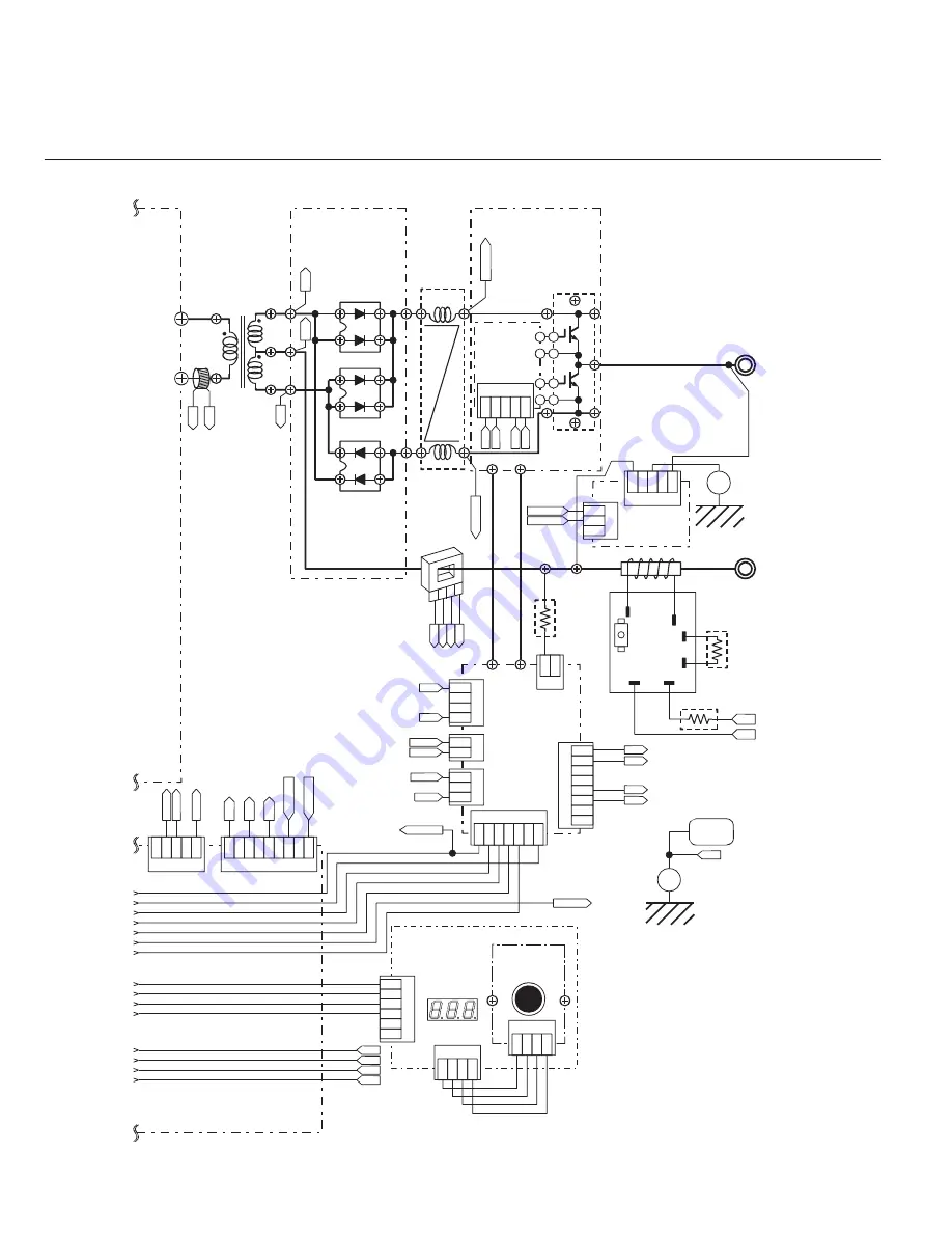
185ACDC / 200ACDC INTERCONNECT DIAGRAM

A10

TB7

TB12

TB21

TB22

TB20

CT2

-Output

Terminal

TO2

PCB12

DIODE Snubber

Circuit Board

[WK-5615]

PCB10

Panel

Circuit Board

[WK-5527]

PCB11

Board

Encoder

[WK-5528]

1 2 3 4

1
2

CN2

3
4
5
6

CN1

1 2 3 4

CN1

-15

+15

IS

GND

EB

AC2

A

C1

AC4

AC2

SH.DET-

SH.DET+

SH.DET-

SIDE CHASSIS 2

FRONT

PANEL

EA

Ground

+

D5

D2

CT2

CT1

CN9

1 2 3 4 5 6 7 8 9

CN8

1 2 3 4 5

HF.UNIT1

CC2

CC1

R1

R2

AC1

AC3

CC1

AC1

AC3

R2

R6

TB1

TB2

CN1

1
2
3
4

P

N

CN2

1
2

P+21V

PGND

CN3

1
2
3

S+15V

SG

CN4

1 2 3 4 5 6 7

1
2

CN6

3
4
5
6
7
8

G7

E7

G8

E8

/RY_ON

R3

PCB13

Super Inpose

Circuit Board

[WK-5569]

HCT1

+Output

Terminal

TO1

FCH1

PCB15

IGBT Gate

Circuit Board

[WK-3367]

G1

E1

E2

G2

G1

E1

G2

E2

PCB14

IGBT Snubber

Circuit Board

[WK-5570]

TB1

TB2

SH.DET+

CN1

1 2 3 4 5

G7

E7

G8

E8

Q13

PCB16

Filter Circuit

Board

[WK-5499]

CN1

1 2 3 4 5

/RY_ON

RY+15V

SIDE CHASSIS 3

CN3

1
2
3

Ground

+

1 2

CN5

D4

AC3

SG

S+15V

RY+15V

AC4

T1

1 2

3 4

-15

+15

IS

GND

Summary of Contents for 185 AC

Page 1: ...SMAW GTAW CC AC DC INVERTER 50 60 Hz ARCMASTER INVERTER ARC WELDERS 185 AC DC 200 AC DC Art A 07227 Service Manual Revision No AE 04 Issue Date May 22 2006 Manual No 0 4884B Operating Features...

Page 2: ......

Page 3: ...st Lebanon New Hampshire USA 03784 603 298 5711 www thermalarc com Copyright 2006 by Thermadyne Industries Inc All rights reserved Reproduction of this work in whole or in part without written permiss...

Page 4: ...Location 3 1 3 03 Electrical Input Connections 3 1 3 04 Electrical Input Requirement 3 1 3 05 Input Power 3 3 3 06 High Frequency Introduction 3 3 3 07 High Frequency Interference 3 4 3 08 Duty Cycle...

Page 5: ...ted Error Codes 10 4 10 04 Verification and Remedy to Failures without Indication Codes 10 8 10 05 Fault Isolation Tests 10 11 10 06 Verification of the Power Input Circuitry 10 12 10 07 Verification...

Page 6: ...Valve SOL1 11 29 11 03 26 Main ON OFF Switch S1 11 29 11 03 27 Input Voltage Switch S2 11 30 11 03 28 Remote Connector CON1 11 31 11 03 29 High Freguency Unit HF UNIT1 11 32 11 03 30 Hall C T HCT1 11...

Page 7: ...electrically live Incorrectly installed or improperly grounded equipment is a hazard 1 Do not touch live electrical parts 2 Wear dry hole free insulating gloves and body protection 3 Insulate yoursel...

Page 8: ...ause fires and burns Accidental contact of electrode or welding wire to metal objects can cause sparks overheating or fire 1 Protect yourself and others from flying sparks and hot metal 2 Do not weld...

Page 9: ...gases 1 Use equipment outside in open well ventilated areas 2 If used in a closed area vent engine exhaust outside and away from any building air intakes WARNING ENGINE FUEL can cause fire or explosi...

Page 10: ...vice on strategies to minimize or avoid potential risks To reduce magnetic fields in the workplace use the following procedures 1 Keep cables close together by twisting or taping them 2 Arrange cables...

Page 11: ...d s la mise en marche En soudage automatique ou semi automatique avec fil ce dernier le rouleau ou la bobine de fil le logement des galets d entrainement et toutes les pi ces m talliques en contact a...

Page 12: ...espace confin que s il est bien ventil sinon portez un respirateur adduction d air Les gaz protecteurs de soudage peuvent d placer l oxyg ne de l air et ainsi causer des malaises ou la mort Assurez v...

Page 13: ...u coupez le fil au tube con tact lorsqu inutilis apr s le soudage 11 Portez des v tements protecteurs non huileux tels des gants en cuir une chemise paisse un pantalon revers des bottines de s curit e...

Page 14: ...LA PEAU ET LES YEUX Les accumulateurs contiennent de l lectrolyte acide et d gagent des vapeurs explosives 1 Portez toujours un cran facial en travaillant sur un accumu lateur 2 Arr tez le moteur avan...

Page 15: ...l copies of this manual may be purchased by contacting Thermal Arc at the address and phone number in your area listed in the inside back cover of this manual Include the manual number and equipment i...

Page 16: ...aker AC Auxiliary Power Remote Duty Cycle Percentage Amperage Voltage Hertz cycles sec Frequency Negative Positive Direct Current DC Protective Earth Ground Line Line Connection Auxiliary Power Recept...

Page 17: ...Pulsed GTAW P Gas Tungsten Arc Welding Sloped GTAW S and Shielded Metal Arc Welding SMAW pr ocesses The power source is totally en closed in an impact resistant flame retardant and non conductive plas...

Page 18: ...nsing Circuit Input Diode Output Diodes Output Inductor Input Power Inrush Current Suppresor IGBT Inverter Module Thermal Sensor Output Transformers Current Transformer CT 1 Capacitor Thermal Sensor C...

Page 19: ...ve electrical parts Disconnect input power conductors from de energized supply line before moving welding power source WARNING FALLING EQUIPMENT can cause serious personal injury and equipment damage...

Page 20: ...2 6 May 22 2006 ARCMASTER 185 ACDC 200 ACDC...

Page 21: ...s that could restrict natural airflow for cooling WARNING Thermal Arc advises that this equipment be electrically connected by a qualified electrician 3 03 Electrical Input Connections WARNING ELECTRI...

Page 22: ...licable electrical codes 2 Connect ends of line 1 BLACK and line 2 WHITE and line 3 RED input conductors to a de energized line disconnect switch 3 Use Table 3 2 and Table 3 4 as a guide to select lin...

Page 23: ...to the welder could occur if 575VAC or higher is applied The following 208 230 460V Primary Current recommendations are required to obtain the maximum welding current and duty cycle from this welding...

Page 24: ...be avoided where possible 4 Re radiation from Unearthed Metallic Objects A major factor contributing to interference is re radiation from unearthed metallic objects close to the welding leads Effecti...

Page 25: ...t u O 0 4 0 4 0 4 e l c y C y t u D 0 9 2 7 0 9 A V K 4 5 4 5 4 5 W K 5 0 5 0 5 0 A V K d a o L o N t u p t u O 3 0 3 0 3 0 W K Input Volts Three Phase Amperage Draw Rated Load No Load Amps Amperage D...

Page 26: ...3 6 May 22 2006 ARCMASTER 185 ACDC 200 ACDC...

Page 27: ...rotate threaded collar fully clockwise 2 1 5 4 3 6 7 8 Front view 8 Socket Receptacle 1 2 3 4 5 6 7 8 5k Ohms GND Figure 4 2 8 Socket Receptacle Socket Pin Function 1 Earth Ground 2 Torch Switch Inpu...

Page 28: ...pply voltage to the equipment 8 SMART Logic Switch Manual slide switch mounted on the back panel selects for proper input voltage If this slide is not set to the position that matches the input voltag...

Page 29: ...d is used to set the start INITIAL CUR current for TIG The Start Current remains on until the torch trigger switch is released after it has been depressed This parameter operates in TIG modes only and...

Page 30: ...d to eliminate the crater that can form at the completion of a weld CRATER CUR This parameter operates in SLOPE or REPEAT 4T TIG modes only and is used to set the finish current for TIG The CRATER Cur...

Page 31: ...WELD CUR TIG 5 to 185A 1 80 A 1 A No Yes Yes 5 to 200A 2 WELD CUR STICK 5 to 160 A 80 A 1 A Yes No No SPOT TIME 0 5 to 5 0 sec 2 sec 0 1 sec No Yes Yes PULSE WIDTH 15 to 80 50 1 No Yes Yes PULSE FREQ...

Page 32: ...ON when not welding and red when welding When in TIG modes VRD is off Control Knob For the selected weld parameter rotating the knob clockwise increases the parameter Rotating the knob counter clockw...

Page 33: ...volt age and as welding arc voltage varies between different classes of electrodes welding current at any one setting would vary according to the type of electrode in use The operator should use the...

Page 34: ...5 2 May 22 2006 ARCMASTER 185 ACDC 200 ACDC...

Page 35: ...ons used to select the parameters to be set The LED s show which function is being adjusted on the Sequence Graph 9 AC DCButton SelectsbetweenACorDCweldingoutput 10 Contactor function Pressing this bu...

Page 36: ...nce The repeat function is operated during the down slope cycle of the Slope Sequence and is active through the down slope period only During the down slope period by opening the Remote Switch contact...

Page 37: ...inutes before opening the enclosure to allow the primary capacitors to discharge To clean the unit open the enclosure refer to Section 10 02 Opening the Enclosure and use a vacuum cleaner to remove an...

Page 38: ...ch body and consumables Visually inspect the cables and leads Replace as needed 3 Months Clean exterior of power supply 6 Months Replace all broken parts Bring the unit to an authorized Thermal Arc Se...

Page 39: ...8 02 Common Welding Operation Faults The following are some of the more common operating faults that occur during welding operations 1 Power Main power not connected Main power not turned on MAIN CIRC...

Page 40: ...Uneven leg length in fillet joint Wrong placement of filler rod Re position filler rod 6 Electrode melts when arc is struck A Electrode is connected to the terminal A Connect the electrode to the term...

Page 41: ...nect the work torch leads to the right welding terminals B Torch lead is disconnected B Connect it to the terminal C Gas flow incorrectly set cylinder empty or the torch valve is off C Select the righ...

Page 42: ...o large for joint Insufficient gap A B C Increase welding current Use smaller diameter electrode Allow wider gap D Incorrect sequence D Use correct build up sequence 4 Portions of the weld run do not...

Page 43: ...d C If very bad chip or grind out irregularities D Lack of penetration with slag trapped beneath weld bead D Use smaller electrode with sufficient current to give adequate penetration Use suitable too...

Page 44: ...s A B Replace gas hose Disconnect gas hose from the rear of Power Source then raise gas pressure and blow out impurities C Gas regulator turned off C Turn gas regulator on D Torch trigger switch lead...

Page 45: ...Have an Accredited Thermal Arc Service Agent or a qualified electrician check for low Mains voltage 4 TIG torch cable and or work lead are too long or leads are coiled E04 error code displayed Output...

Page 46: ...d Pre charge abnormality Due to malfunction inside the Welding Power Source primary capacitors are not charging correctly Have an Accredited Thermal Arc Service Agent service the machine No weld curre...

Page 47: ...t least once every 3 months and B For fixed equipment at least once every 12 months The owners of the equipment shall keep a suitable record of the periodic tests NOTE A transportable power source is...

Page 48: ...sts on the top of the unit Place a small flat bladed screw driver between the cover hinge on the front panel Gently lift the cover hinge out of the front cover mounting hole Remove the control s clear...

Page 49: ...d by removing the side covers VR1 Art A 07081 Figure 9 3 VRD ON OFF Step C and D D Turning the VRD ON OFF see Figure 9 3 To turn VRD ON rotate the trim potentiometer on the display PCB fully clockwise...

Page 50: ...9 4 May 22 2006 ARCMASTER 185 ACDC 200 ACDC...

Page 51: ...er subassemblies of this unit Evidence of unauthorized repairs will void the factory warranty If a subassembly is found to be defective by executing any of the procedures in this Service Manual the su...

Page 52: ...ion panel Wait at least 5 minutes for the discharge to complete 2 Remove all screws and nuts on the side covers Art A 05661 Figure 10 2 Screws and Nuts 3 Loosen the screws on the front panel and the r...

Page 53: ...emove the side covers Art A 05664 Figure 10 5 Remove Side Covers 6 Remove protection cover sheet by removing the plastic tabs 1 1 1 1 2 Art A 05665 Figure 10 6 Protection Cover NOTE When you re assemb...

Page 54: ...nd rear airflow paths Cleaning and removing dust from the front and rear panels once every six months in a normal working environment is recommended Extremely dusty environments will require more freq...

Page 55: ...he secondary IGBT Q13 Refer to section 10 07 5 for the test Refer to section 11 3 33 for the replacement e Replace the Hall CT HCT1 NOTE Pay special attention to installed direction of HCT1 The Hall C...

Page 56: ...ction 11 3 5 8 E82 Rated Voltage Selection Circuit abnormality Cause Rated voltage selection circuit inside the Welding Power Source is not functioning properly Verification Remedy a Verify the wiring...

Page 57: ...er to section 11 3 2 11 3 4 11 E94 Thermistor malfunction Cause Thermistors for detecting temperature of internal components have malfunctioned Verification Remedy a Confirm a secure connection of the...

Page 58: ...try of the cooling fan FAN1 on PCB3 Verify the drive circuitry of the cooling fan FAN1 on PCB3 Refer to section 10 07 1 Replace PCB3 if necessary Refer to section 11 3 4 2 Gas Valve Failure No Gas flo...

Page 59: ...t there is no open circuit on the remote connector at TIG Torch side In equipment for remote control use confirm the pin specification of the connector Refer to page 4 1 b Verify the condition and con...

Page 60: ...unit will generate a High Voltage component that can cause extreme personal harm and test equipment damage Capacitors installed inside the Welding Power Source are electrically charged for a while af...

Page 61: ...burnt cracked etc replace R6 Refer to section 11 3 19 f Replace the High Frequency Unit HF UNIT1 Refer to section 11 3 29 g Replace PCB3 WK 5548 Refer to section 11 3 4 10 05 Fault Isolation Tests Pre...

Page 62: ...elding may cause the input voltage to decrease to a value below the operating range of the unit 3 Verify input voltage after the input switch S1 using an AC voltmeter The capability of the voltmeter s...

Page 63: ...the above voltage is still abnormal replace PCB1 WK 5477 10 07 Verification of Power Supply Voltage CAUTION Before performing any portion of the procedure below make certain the unit is placed in the...

Page 64: ...f CN11 on PCB3 WK 5548 The location of connector CN11 of PCB3 is indicated in Figure 11 12 When you measure the above voltage do not remove the connector Conduct the measurement while the connector pl...

Page 65: ...13 Verification of the SOL1 2 Using the measurement taken above follow the chart below for possible failure modes 3 Verification of the primary Diode D1 1 Verify the characteristic of the primary dio...

Page 66: ...e 10 6 Tester checkpoints for D2 D4 and D5 Anode Anode Cathode Cathode Figure 10 15 Tester checkpoints for D2 D4 and D5 5 Verification of the primary IGBT Q1 Q12 1 Check whether there are any abnormal...

Page 67: ...CK mode In STICK welding mode mark and then turn potentiometer VR1 on PCB6 WK 5549 fully counter clockwise to turn off the electric shock protector function Voltage Reduction Device VRD Contactor func...

Page 68: ...he OCV using a DC voltmeter The capability of the voltmeter should be more than 100VDC The check point with a tester is the voltage between output terminal and In TIG mode the OCV ceases 3 seconds aft...

Page 69: ...314 2 PCB10 Printed Circuit Board WK 5527 11 14 W7001319 3 PCB11 Printed Circuit Board WK 5528 11 15 W7001320 4 PCB12 Printed Circuit Board WK 5615 11 16 W7001594 5 PCB13 Printed Circuit Board WK 5569...

Page 70: ...8 W7001407 4 PCB4 Printed Circuit Board WK 4819 11 11 10 6635 5 PCB5 Printed Circuit Board WK 5551 11 12 W7001417 6 PCB6 Printed Circuit Board 185ACDC WK 5549 11 12 W7001725 6 PCB6 Printed Circuit Boa...

Page 71: ...5 W7001384 2 CT2 Current Trans 11 16 W7001304 3 D1 Primary Diode 11 34 10 6628 4 D2 Secondary Diode 11 34 10 6629 5 D4 Secondary Diode 11 34 10 6629 6 D5 Secondary Diode 11 34 10 6629 7 FCH1 Reactor 1...

Page 72: ...WK 3367 11 35 10 6643 4 R3 Discharge Resistor 11 22 10 5137 5 R4 Current Limiting Resistor 11 24 W7001452 6 R5 Current Limiting Resistor 11 24 W7001452 7 R6 Resistor on High Frequency Unit 11 24 W7001...

Page 73: ...NOTE During your maintenance or repair please cut any tie wraps necessary However after your maintenance or repair please reassemble and tie wrap all components and wiring in the same manner as before...

Page 74: ...3 Remove the PCB8 WK 5479 Reference page 11 13 4 Remove the PCB9 WK 5479 Reference page 11 13 5 Remove the four screws Pull out the Rear Control Cover and bring it down 6 Remove the five screws and th...

Page 75: ...Reference page 10 2 2 Disconnect the 13 connectors 3 Remove the four screws and two ground terminals 4 Remove the PCB3 PCB4 PCB5 PCB6 and PCB7 unit and then disconnect the two connectors Remove the In...

Page 76: ...the PCB2 WK 5596 6 Disconnect the three connectors and two terminal from the PCB2 WK 5596 3 3 PCB2 WK 5482 V 200ACDC only 1 Remove the Side Panel Reference page 10 2 2 Disconnect the 13 connectors 1 2...

Page 77: ...he four screws and two ground terminals 4 Remove the PCB3 PCB4 PCB5 PCB6 and PCB7 unit and then disconnect the two connectors Remove the Insulated Sheet 5 Remove seven screws and five terminals Remove...

Page 78: ...e page 10 2 2 Remove PCB4 WK 4819 Reference page 11 11 3 Remove PCB6 WK 5549 Reference page 11 12 4 Remove PCB7 WK 5550 Reference page 11 12 5 Disconnect the 11 connectors 6 Remove the four screws and...

Page 79: ...3 WK 5548 Remove the one screw and one ground terminal from the PCB5 WK 5551 8 Disconnect the two connectors from the PCB3 WK 5548 3 5 PCB4 WK 4819 V 1 Remove the Side Panel Reference page 10 2 2 Remo...

Page 80: ...ctors 3 Remove the three screws and five connectors Remove the PCB6 WK 5549 3 7 PCB7 WK 5550 V 1 Remove the Side Panel Reference page 10 2 2 Remove the PCB6 WK 5549 Reference page 11 12 3 Remove the t...

Page 81: ...the four screws and two IGBT Chassis 3 Remove the two connectors and three screws Remove the PCB8 WK 5479 Remember to install silicone rubber sheets when reinstalling the PCB8 WK 5479 3 9 PCB9 WK 547...

Page 82: ...r sheets when reinstalling the PCB9 WK 5479 3 10 PCB10 WK 5527 V 1 Remove the Side Panel Reference page 10 2 2 Remove the PCB11 WK 5528 Reference page 11 15 3 Remove the three latches of Front Control...

Page 83: ...nce page 10 2 2 Remove the Protection Cover 3 Remove the Knob Cap Holding the Knob down loosen the screw and remove the Knob 4 Disconnect the one connector from the PCB10 WK 5527 Remove the four screw...

Page 84: ...m the PCB11 WK 5528 3 12 PCB12 WK 5615 Transformer T1 Current Trans CT2 VX 1 Remove the Side Panel Reference page 10 2 2 Remove PCB13 WK 5569 Reference page 11 19 3 Disconnect the one connector and cu...

Page 85: ...ARCMASTER 185ACDC 200ACDC 11 17 5 Open the Dust Cover Sheet Remove the three screws and three terminals 6 Remove the 16 screws 7 Remove the PCB12 and T1 unit 1 2 2 2...

Page 86: ...remove the Current Trans CT2 9 Remove the Dust Cover Sheet Extend the electrode and remove the T D Bus Bar1 T D Bus Bar2 and T Center Bus Bar 10 Remove the two PCB supporters and cushion Remove the fo...

Page 87: ...e 10 2 2 Remove the Nylon Hose Remove the four screws Remove the two terminals and open the Rear Panel 3 Disconnect the six connectors and remove the two screws and two terminals 4 Remove the two scre...

Page 88: ...ose 3 Disconnect the two connectors Remove the three PCB supporters and remove the PCB16 WK 5499 3 15 PCB14 WK 5570 V 1 Remove the Side Panel Reference page 10 2 2 Remove the PCB16 WK 5499 Reference p...

Page 89: ...1 4 Remove the three PCB supporters from the PCB14 WK 5570 3 16 PCB17 WK 4917 V 1 Remove the Side Panel Reference page 10 2 2 Remove the six screws and six terminals 3 Remove the four screws and then...

Page 90: ...rminal and remove the PCB17 unit 5 Remove the two screws and remove the S1 Bus Bar from the PCB17 WK 4917 3 17 Discharge Resistor R3 VX 1 Remove the Side Panel Reference page 10 2 2 Remove the Nylon H...

Page 91: ...185ACDC 200ACDC 11 23 3 Remove the four screws and open the Front Panel 4 Cut the one snap band and disconnect the one connector 5 Remove the one screw and one nut and remove the one terminal 1 1 1 1...

Page 92: ...ference page 10 2 2 Remove the PCB2 WK 5596 Reference page 11 7 3 Remove the one screw and remove the Current Limiting Resistor R4 R5 3 19 Resistor on High Frequency Unit R6 VX 1 Remove the Side Panel...

Page 93: ...e Side Panel Reference page 10 2 2 Remove the Nylon Hose Remove the two bolts two toothed washers one washer and one terminal 3 Remove the four screws and open the Front Panel 4 Remove the two termina...

Page 94: ...Remove the Side Panel Reference page 10 2 2 Remove the PCB16 WK 5499 Reference page 11 20 3 Remove the PCB14 WK 5570 Reference page 11 20 4 Remove the Coupling Coil CC1 Reference page 11 25 5 Remove t...

Page 95: ...G 747 or equivalent on the base 3 23 Secondary Thermistor TH2 UVX 1 Remove the Side Panel Reference page 10 2 2 Remove the PCB13 WK 5569 Reference page 11 19 3 Remove the PCB12 WK 5615 Reference page...

Page 96: ...e the Nylon Hose Remove the four screws Remove the two terminals and open the Rear Panel 3 Cut the four snap bands and disconnect the one connector 4 Remove the two screws and detach the Cooling Fan F...

Page 97: ...e the four screws Remove the two terminals and open the Rear Panel 3 Remove the C ring and detach the Solenoid Valve SOL1 When reinstalling make sure that the C ring seats in the solenoid valve groove...

Page 98: ...he two screws and detach the Main ON OFF Switch S1 Remove the three posts 3 27 Input Voltage Switch S2 UV 1 Remove the Side Panel Reference page 10 2 2 Remove six screws and six terminals 3 Remove fou...

Page 99: ...Remove the two screws and two nuts and then remove the Input Voltage Switch S2 3 28 Remote Connector CON1 V 1 Remove the Side Panel Reference page 10 2 2 Remove the Protection Cover 3 Remove the four...

Page 100: ...ectors Remove the one screw and two ground terminals 5 Remove the two screws and Remote Socket CON1 3 29 High Freguency Unit HF UNIT1 V 1 Remove the Side Panel Reference page 10 2 2 Remove the High Fr...

Page 101: ...High Freguency Unit HF UNIT1 3 30 Hall C T HCT1 UV 1 Remove the Side Panel Reference page 10 2 2 Remove the Nylon Hose Remove the four screws Remove the two terminals and open the Rear Panel 3 Remove...

Page 102: ...e two screws and four terminals Remove the two screws and then detach the Primary Diode D1 Before installing a new diode apply a uniform coat of silicone compound Shinetsu Silicone G 747 or equivalent...

Page 103: ...a uniform coat of silicone compound Shinetsu Silicone G 747 or equivalent on the base 3 33 Secondary IGBT Q13 PCB15 WK 3367 UV 1 Remove the side cover Reference page 10 2 2 Remove the PCB16 WK 5499 Re...

Page 104: ...200ACDC 11 36 6 Remove the one connector and two screws and remove the Secondary IGBT Q13 Before sinstalling a new IGBT apply a uniform coat of silicone compound Shinetsu Silicone G 747 or equivalent...

Page 105: ......

Page 106: ...CT 1 40 1 4 D1 10 6628 Diode gen 3 1 IPS DFA50BA160 185ACDC 1 4 D1 10 6769 Diode gen 3 1 IPS DFA100BA160 200ACDC 1 5 D2 10 6629 Diode gen 3 1 IPS DBA200UA60 1 6 D4 10 6629 Diode gen 3 1 IPS DBA200UA6...

Page 107: ...Label Side gen 3 1 IPS N4A785200 2 48 W7001339 Label 1 Warning gen 3 1 IPS N1B029700 1 49 W7001340 Label 2 Warning gen 3 1 IPS N1B029800 1 50 10 6658 Label Output Term gen 3 1 IPS N4A040100 1 51 10 67...

Page 108: ...185ACDC 200ACDC PARTS LI ST A 3 48 47 45 40 84 33 34 42 52 27 69 69 74 74 59 58 39 56 51 8 53 54 35 40 85 50 57 56 57 2 38 46 43 22 21 41 67 65 66 44 49 47 55...

Page 109: ...85ACDC 200ACDC PARTS LIST A4 37 5 6 7 23 18 17 19 16 15 81 20 62 62 62 62 20 68 68 14 13 80 63 4 31 31 30 10 64 11 29 12 36 83 32 37 61 76 60 60 79 79 82 79 64 9 28 75 1 25 71 70 77 73 72 24 26 79 3 7...

Page 110: ...l PCB17 CN1 F PCB3 CN7 l CT2 G PCB3 CN11 l FAN1 H SOL1 I PCB3 CN20 l PCB8 CN1 J PCB3 CN21 l PCB8 CN2 K PCB3 CN22 l PCB9 CN1 L PCB3 CN23 l PCB9 CN2 M PCB3 CN18 l PCB7 CN20 N PCB3 CN33 l PCB6 CN20 O PC...

Page 111: ...PCB3 PCB2 HCT1 PCB13 PCB16 CN2 CN1 CN2 CN1 CN1 CN4 CN7 CN20 CN8 CN9 CN33 CN21 CN17 CN1 CN22 CN11 CN23 CN20 CN14 CN15 CON1 CN3 S2 CN20 CN21 CN1 CN2 CN3 CN1 CN4 TH1 TH2 CN3 D1 PCB17 FAN1 SOL1 CN1 CN2 CN...

Page 112: ...t Board WK 5548 PCB1 Main Circuit Board WK 5493 3 CN1 1 2 3 PCB6 Control Circuit Board WK 5549 CT2 CT1 SIDE CHASSIS 1 REAR PANEL E CN3 1 2 G1 E1 G2 E2 G3 E3 PCB5 Conect Circuit Board WK 5551 CN30 CN31...

Page 113: ...CN8 1 2 3 4 5 HF UNIT1 CC2 CC1 R1 R2 AC1 AC3 CC1 AC1 AC3 R2 R6 TB1 TB2 CN1 1 2 3 4 P N CN2 1 2 P 21V PGND CN3 1 2 3 S 15V SG CN4 1 2 3 4 5 6 7 1 2 CN6 3 4 5 6 7 8 G7 E7 G8 E8 RY_ON R3 PCB13 Super Inp...

Page 114: ...ircuit Board WK 5493 3 CN1 1 2 3 PCB6 Control Circuit Board WK 5549 CT2 CT1 SIDE CHASSIS 1 REAR PANEL E CN3 1 2 G1 E1 G2 E2 G3 E3 PCB5 Conect Circuit Board WK 5551 CN30 CN31 CN31 CN30 CN32 CN32 PCB7 F...

Page 115: ...9 CN8 1 2 3 4 5 HF UNIT1 CC2 CC1 R1 R2 AC1 AC3 CC1 AC1 AC3 R2 R6 TB1 TB2 CN1 1 2 3 4 P N CN2 1 2 P 21V PGND CN3 1 2 3 S 15V SG CN4 1 2 3 4 5 6 7 1 2 CN6 3 4 5 6 7 8 G7 E7 G8 E8 RY_ON R3 PCB13 Super In...

Page 116: ...eter positive lead to the anode positive of the diode and the negative lead to the cathode negative of the diode refer to Figure 13 1 A properly functioning diode will conduct in the forward bias dire...

Page 117: ......

Page 118: ...herwise shall not exceed the price of the goods upon which such liability is based No employee agent or representative of thermal arc is authorized to change this warranty in any way or grant any othe...

Page 119: ...including but not limited to relays switches contactors solenoids fans electric motors 1 year 1 year PLASMA WELDING EQUIPMENT WARRANTY PERIOD LABOR Ultima 150 Original Main Power Magnetics 5 years 3 y...

Page 120: ......

Page 121: ...trict Shanghai PR 200052 Telephone 86 21 69171135 Fax 86 21 69171139 Thermadyne Asia Sdn Bhd Lot 151 Jalan Industri 3 5A Rawang Integrated Industrial Park Jln Batu Arang 48000 Rawang Selangor Darul Eh...

Page 122: ...World Headquarters Thermadyne Holdings Corporation Suite 300 16052 Swingley Ridge Road St Louis MO 63017 Telephone 636 728 3000 Fascimile 636 728 3010 Email sales thermalarc com www thermalarc com...

Reviews: