background image

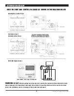
Install the remote control panel in a central area of the structure 
where it will sense the relative humidity of the structure accurately. 
Do not install the control panel where it may not accurately sense 
the relative humidity such as near HVAC supply registers, near 
exterior doors, or near a pool or spa. The installer must supply the 
wiring between the Ultra-Aire XT150H and the control panel. Be 
sure to safely route the control wiring to prevent damage during 
installation. Be careful not to cross the wires when connecting the 
Ultra-Aire XT150H and the remote control panel or damage to the 
transformer may result. 

The remote controls of the Ultra-Aire XT150H are powered by a low 
voltage circuit (24 Vac) and must NEVER contact or be connected 
to a high voltage circuit. The control wires leaving the Ultra-Aire 
XT150H and the remote control panels are numbered and color-
coded to prevent confusion. Some of the control wires leaving the 
Ultra-Aire XT150H may not be used with certain control panels and 
should be left safely disconnected with wire nuts taped onto the 
stripped ends. Be sure to consult the electrical schematic in this 
manual or inside the access panel of the Ultra-Aire XT150H before 
making the control connections. 

3.3 Condensate Water Removal 

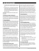
Condensate drains by gravity via the drain port. Use 3/4" male NPT 
PVC pipe. Route drain pipe to drain. Install a trap if possible. Take 
care when installing drain pipe to drain port. Use an adjustable 
wrench to secure the drain port. An optional condensate pump kit 
may be installed if a lift is required to dispose of the condensate. 
The condensate pump kit can be ordered directly from the factory. 
See the optional parts list for information on the kit. 

3.4 Ducting 

3.4A Installing Duct Collars 

The Ultra-Aire XT150H is equipped with 10" and 6" round inlet 
collars and a 10" round (ovaled) exhaust collar. Follow instructions 
included with collars.

3.4B Ducting for Dehumidification 

For the ideal installation, draw air from the central part of the 
home and return it to the isolated areas of the home like the 
bedrooms, den, utility room, or family room. The ductwork of the 
existing heating system can be used to supply air to the home. If 
the existing supply goes to isolated areas of the home, discharge 
the supply of the Ultra-Aire XT150H into the supply of the existing 
heating system. If the existing heating system incorporates a 
central supply, installation of a separate supply duct from the Ultra-
Aire XT150H to each isolated area is recommended. DO NOT draw 
air directly from the kitchen, laundry, or isolated basement. You 
may draw air from a basement that is open to the home. All flexible 
ducting connected to the Ultra-Aire XT150H should be UL listed. 

The inlet of the Ultra-Aire XT150H is the 10" diameter hole in the 
filter enclosure of the unit. A 10" round collar is supplied with the 
unit to attach to round duct. The duct may be permanently attached 
to the collar. A 6" round collar is provided with the unit to attach to 
the 6" hole in the filter enclosure. The 6" collar should be capped 
if fresh make-up air is not desired. If fresh make-up air is desired, 
see Section 3.4C. 

A 10" round (ovaled) collar is supplied with the unit for the outlet of 
the Ultra-Aire XT150H.  

A length of flexible ducting on all Ultra-Aire XT150H duct 
connections is recommended to reduce noise and vibration 
transmitted to rigid ductwork in the structure. 

Ducting the Ultra-Aire XT150H as mentioned in Sections 3.4A-3.4G 
requires consideration of the following points: 

Duct Sizing: For total duct lengths up to 25', use a minimum 10" 
diameter round or equivalent rectangular. For longer lengths, use a 
minimum 12" diameter or equivalent. Grills or diffusers on the duct 
ends must not excessively restrict airflow. 

Isolated Areas: Effective dehumidification may require that ducting 
be branched to isolated, stagnant areas. Use 8" or larger diameter 
branch ducting to each of two or three areas, use 6" or larger to 
each of four or more areas. 

Connecting to existing HVAC systems: An optional 10" check 
damper is available from the factory to prevent reverse flow 
through the Ultra-Aire XT150H. If the Ultra-Aire XT150H is ducted 
to the supply ducting air handler, it is recommended that the check 
damper be placed in the Ultra-Aire XT150H supply duct. Contact 
the factory when connecting to a static pressure of greater than or 
equal to +.5" WG. 

FOR HVAC INSTALLER ONLY

5

Ultra-Aire XT150H Installer’s & Owner’s Manual

1.00"

External drain trap on unit
is recommended

Summary of Contents for Ultra-Aire XT150H

Page 1: ...tdoor air may be ducted to the unit via a six inch round duct This provides fresh air to dilute pollutants and maintain high oxygen content in the air The amount of fresh air ventilation can be regula...

Page 2: ...igital Control WITHOUT Fresh Air 9 4 2 Humidity Control Adjustment 8 4 3 Fan Filter Switch 8 4 4 Ventilation Timer 8 4 4A Setting the Time 9 4 4B Ventilation Schedule 9 4 4C Automatic or Manual Mode 9...

Page 3: ...th space to access the back or side panels for maintenance and service DO NOT INSTALL UNIT WITH THE SERVICE PANELS INACCESSIBLE Avoid directing the discharge air at people or over the water in pool ar...

Page 4: ...l vibration and or noise A drain pan MUST be placed under the unit if installed above a living area or above an area where water leakage could cause damage Place the Ultra Aire XT150H on supports that...

Page 5: ...ating system can be used to supply air to the home If the existing supply goes to isolated areas of the home discharge the supply of the Ultra Aire XT150H into the supply of the existing heating syste...

Page 6: ...lter enclosure of the unit The 6 round collar includes a manual damper Adjust the manual damper to provide the desired amount of fresh air for ventilation The amount of fresh air should be based on th...

Page 7: ...edrooms den etc By ducting this way the air inside the structure will circulate through the Ultra Aire XT150H to be filtered and dehumidified Avoid discharging all the air from the dehumidifier in one...

Page 8: ...ir Refer to Section 5 4 2 Humidity Control Adjustment Set the humidity control to the desired humidity level for the home Turning the knob clockwise results in a drier setting See the back of the cont...

Page 9: ...the week for this program You can choose Mon Sun Mon Fri Sat Sun or any single day of the week The days chosen are shown along the top of the display on the ventilation timer Next press the h button...

Page 10: ...e lead from the unit or damage to the transformers will result Do not direct connect the white lead on the unit to the violet lead on the ventilation control or damage to the transformer will result H...

Page 11: ...ty Range Accuracy 10 95 RH 5 Auxillary Relay Capacity 5 Amps 24VAC Temp Range Accuracy 30 90 F 2 Size 4 95 L x 1 06 W x 4 19 H Major Operations n Digital control of Relative Humidity Digital Set Point...

Page 12: ...heck and clean the screen on the outdoor fresh air return seasonally The screen may become plugged during the seasons when there are many particles in the outdoor air 7 Service 7 1 Warranty A warranty...

Page 13: ...uch as expected 1 Air temperature and or humidity have dropped 2 Humidity meter and or thermometer used are out of calibration 3 Unit has entered defrost cycle Sec 5 8 4 Air filter dirty Sec 4 1 4 2 5...

Page 14: ...capacitor Plug in and turn on the unit If the compressor fails to start replace the run capacitor 11 If the unit still does not start adding a hard start kit relay capacitor will provide greater start...

Page 15: ...and bring in fresh air from outside The ventilation timer should be set for the required ventilation of the residence The home should be ventilated with fresh air as suggested by applicable codes and...

Page 16: ...Aire XT150H to the blue 5 lead on the control panel If the pump fails this switch opens the compressor control circuit and stops water production before the reservoir overflows The Ultra Aire XT150H...

Page 17: ...FOR HVAC INSTALLER ONLY 17 Pictorial Electrical Diagrams of Ultra Aire XT150H Ultra Aire XT150H Installer s Owner s Manual...

Page 18: ...t No Qty Description 12 4026687 1 45mFd CAPACITOR COMPRESSOR 13 4022487 1 TRANSFORMER 14 4022484 1 RELAY COMPRESSOR 15 4017021 1 15mFd CAPACITOR IMPELLER 16 4026932 1 COLLAR 10 INCH 17 4026947 1 COLLA...

Page 19: ...Electrically Actuated not shown 32 4024153 1 Cover for Items 28 29 not shown 33 4021495 1 Knob Black 25 shaft 34 4024150 1 Instructions Humidity Fan not shown 35 4024122 1 Instructions Ventilation Ti...

Page 20: ...ng door shut Once the door is shut release the door latch Collar Install Remove the 2 round ducts 3 seals and small bag of mounting hardware from inside the rectangle opening Adhere seals onto the bac...

Page 21: ...costs related to changes to a Product or Component that may be required by any codes laws or regulations that may become effective after initial purchase of the Product by Customer Customer Responsib...

Page 22: ...any form or by any means electronic or mechanical for any purpose without the express written permission of Therma Stor LLC 2007 Therma Stor LLC All rights reserved PO Box 8680 Madison WI 53708 Phone...

Reviews: