


P.9
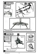
Please refer to attached sheet for linkage connector installation.
Servo Set
3x3mm
Set Screw
Linkage Connector
M2
Nut
2mm
Washer
3
3
3
3
LINKAGE CONNECTOR
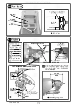
12
Thr
ott
le P
ush
wir
e
3mm
Included with the radio
Set.
Throttle Servo.
2mm
2mm
M2 Nut
2mm
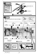
Servos
13
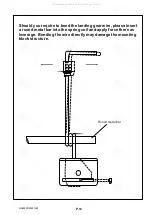
Install and arrange the servo as shown in the diagram.
Front
Throttle pushrod
Ø1.2x350mm
Bottom View
Throttle Servo
Plywood
3x12x119mm
Elevator
Servo
Pushrod
Connector
(
J1
)
Pushrod Ø1.8x70
J1
J2
KM2x8mm
M2 Nut
Elevator Pushrod
Ø1.8x70mm
Plastic Tube
d2xD3x170mm
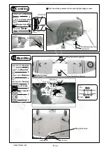
Battery
Copper Tube
Press down the center
1/3 portion
1mm
Balsa
8x8x62mm
Switch
Elevator Servo
Balsa
6x62x125mm
Rigging Z Bend
Straper
Balsa
8x8x62mm
Rudder Servo
Balsa
8x8x62mm
Balsa
8x8x62mm
Fuel Tube
Ø6x5mm
Balsa
6x62x125mm
GA026PO29451405
All manuals and user guides at all-guides.com


