background image


CONNECTING THE HANDLES 


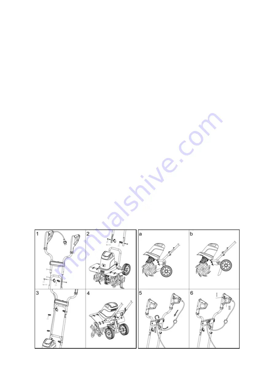
Attach the Middle Handle (2) onto the Lower Guide Handle (4) and secure it using two M6x45 
screws and swing nuts supplied. 

(Image 2)


Connect the Top Handle (1) to the Middle Handle (2) and secure it by two supplied screws and 
swing nuts. 

(Image 1)


Tighten all screws and nuts completely. 


Using the two supplied cable clips (3) affix the electrical cable to the Handles. 

(Image 3).


OPERATION


Before operating the machine, please ensure you are fully aware of the below instructions, failure 

to do so, could invalidate your manufacturer’s warranty. Completely unwind the electrical cable.  


ADJUSTING THE SPUR 

The position of the spur defines the working depth. 

(Image 4)


Image A - Use this position for transportation.  


Press the button to release the wheels. Pull the wheels down until the lock piece engages into 
the recess on the other side of the frame. Release the button and make sure the frame is locked 
firmly.  

Image B - Use this position for working.  


Press the button to release the wheels. Pull the wheel up until the lock piece engages into the 
recess on the other side of the frame. Release the button and make sure the frame is locked 
firmly.  


STARTING 

Image 6 


Use your thumb to press the safety button (I) on the left side of the right handle and then press 
the trigger (II). 


The safety button is only used as a release, so that the motor can be started and does not have 
to be depressed, once the motor has been started.  


To turn the motor off, simply release the operation switch (II). 


Summary of Contents for 193855002

Page 1: ... SPARES SUPPORT 01793 333212 Please read understand this manual paying attention to the safety instructions before use The manufacturer reserves the right to change the product specification and livery according to continued product improvements All images used are for illustration purposes only INSTRUCTION MANUAL ...

Page 2: ......

Page 3: ...r machine please contact us Tel 01793 333212 Email customerservice handydistribution co uk Monday to Friday 8 00am to 5 30pm excl Bank Holidays SPECIFICATIONS The manufacturer reserves the right to change the product specification and livery according to continued product improvements Model THET1400 Product Number 193855002 Motor Power 1400 watt Motor Voltage 230V 50HZ Idle Speed 330min 1 Working ...

Page 4: ...ren or pets are nearby Keep in mind that the operator or user is responsible for accidents or hazards involving the machine that occur to other people or their property ELECTRICAL REQUIREMENTS Connect the main leads to a standard 230V 10 50Hz 1Hz electrical supply which has protection devices for under voltage over voltage over current as well as a residual current device RCD with maximum residual...

Page 5: ...approached stop the machine immediately E DO NOT use the machine in wet weather conditions F CAUTION Stop the machine immediately if the power cable or plug becomes damaged G Disconnect from power supply when not in use before moving adjusting changing parts cleaning or working on the machine Never open the motor cover before disconnecting the electrical plug from the power supply Safety alert sym...

Page 6: ...ck that the electric circuit is adequately protected and that it corresponds with the power voltage and frequency of the motor Check that there is a ground connection and a regulation differential switch further up the circuit Ground the log splitter Prevent body contact with grounded surfaces pipes radiators ranges and refrigerator enclosures Never open the pushbutton box on the motor Should this...

Page 7: ...electrical and electronic equipment For more detailed information about recycling of this product please contact your local council office your household waste disposal service or shop where you purchased the product ELECTRICAL CONNECTION Do not connect either core to the earth pin The insulation on the grounded three metre electrical cord will only remain effective if the original insulating part...

Page 8: ...ou require any assistance with regards to the contents of the Tiller please contact us Tel 01793 333212 Email customerservice handydistribution co uk Monday to Friday 8 30am 5 30pm excl Bank Holidays Description 1 Top Handle 2 Middle Handle 3 Cable Clip 4 Lower Guide Handle 5 Motor Housing 6 Fender 7 Tines 8 Wheel ...

Page 9: ...nes the working depth Image 4 Image A Use this position for transportation Press the button to release the wheels Pull the wheels down until the lock piece engages into the recess on the other side of the frame Release the button and make sure the frame is locked firmly Image B Use this position for working Press the button to release the wheels Pull the wheel up until the lock piece engages into ...

Page 10: ...ack to you the tiller will be most effective If the tiller digs deep enough to stay in one spot gently rock the tiller side to side to start the tiller moving forward again For preparing a seed bed we recommend you apply one of the tilling patterns shown in Image 7 A Make two passes over the area to be tilled the second at a right angle to the first B Make two passes over the area to be tilled the...

Page 11: ...om the mains Thoroughly clean the machine at the end of each day s operation Clean the underside of the housing around the tines protective shield and fender with a scrubbing brush and brush or soft cloth dampened with a mild soap and water mixture Never splash with water To remove soil and debris from the tines and transmission use a stiff brush or a dampened cloth Clean the air vents and remove ...

Page 12: ...iller on its left side and clean the transmission housing before removing the drain plug to prevent dirt and debris from getting into the gearbox Using a 5mm Allen key unscrew both plugs If necessary disassemble tines We recommend MOBILUX EP 023 grease and filled using a grease gun 90g will fill an empty gearbox until it begins to seep out around the edge of the hole of the nozzle Check the O ring...

Page 13: ...me ground multiple times to reach required depth Unusual Noise 1 Tines are blocked 2 Gearbox oil leak 3 Loose nuts bolts or other fastening 1 Switch off the machine wait for remove the plug from the mains 2 Contact your local approved dealer 3 Tighten all if noise continues contact your local approved dealer Excessive Vibration 1 Tines are damaged or worn 2 Working depth too deep 1 Replace the tin...

Page 14: ...PARTS DIAGRAM THET1400 193855002 ...

Page 15: ...30020800 Nut M8 4 50 TH165 12 Screw ST3 9x19 6 17 TH165 25 Blade Set Right A 1 51 TH217 192241245000 Rubber Seal 1 18 TH217 202211020020 Ring 2 52 TH217 182257001200GM Motor Housing 1 19 TH217 212241230080 Transmission Case Right 1 53 TH217 182257004200 Label 1 20 TH165 29 Rubber Seal Φ19 Φ27 4 5 2 54 TH165 21 Cable Holder 1 21 TH165 30 Oil Bearing 2 55 TH217 182257002200 Upper Housing 1 22 TH217 ...

Page 16: ......

Page 17: ......

Page 18: ...Directive The conformity assessment procedure followed was in accordance with EN 55014 1 20016 A1 A2 EN55014 2 1997 A1 A2 EN 61000 3 2 2006 A1 A2 EN 61000 3 3 2013 EN ISO 3744 2010 EN 709 1997 A4 EN 60335 1 2012 EN 62233 2008 Notified Body TUV Rheinland LGA Products GmbH Addresses Tillystrasse 2 90431 Nurnberg GERMANY Additional Information Guaranteed Sound Power LWA 93dB A Max Measured Vibration ...

Page 19: ......

Page 20: ...il customerservice handydistribution co uk Monday to Friday 8 00am to 5 30pm excl Bank Holidays To see our range of garden machinery equipment visit www thehandy co uk Making gardening easier affordable since 1938 Distributed by Handy Distribution Murdock Road Dorcan Swindon SN3 5HY ...

Reviews: