


Assembly
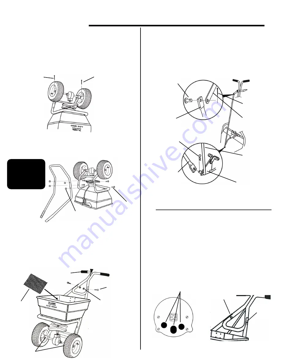
Turn the spreader upside-down. Place the
wheels on the axle with the longer portion of the
hubs facing inward. Secure the drive wheel “A” (right
side) to the axle using the 3/16” cotter pin. Attach the
idler wheel “B” (left side) to axle. Then insert the 1/8”
cotter pin through the axle and secure.
Attach the leg/brace to the frame as shown using
(4) 1/4-20 x 2 1/4” carriage bolts and lock washers,
and nuts.
2)
1)
Turn spreader upright on wheels. Insert screen into
hopper sliding it under the screen clips. Attach the
upper handle assembly to the handle brace with the
handle lever facing as shown. Secure with (2) 1/4-20 x 1
1/2” carriage bolts, lock washers, and nuts. Using a
grease gun, lubricate the grease fittings on the axle
.
3)
Install control tube to the handle lever with
(1) 1/4 dia. clevis pin and a 3/32” dia. cotter pin.
Remove the paper tube on the end of the lower control
rod and slip opposite end of control tube over the rod
making sure the pivot lever is between the lower rod
and the control tube. Secure with a hitch pin cotter.
4)
2
1/8” Cotter Pin
B
A
3/16” Cotter Pin
CHECK SPREADER FOR COMPLETE SHUTOFF
.
Pull the on/off control lever back to the “OFF”
position. Determine if the holes in the hopper are
completely closed as shown below. Also make sure shut
off plate is not closing too far which will cause the control
lever to bind. If adjustment is needed, loosen
the two
carriage bolts holding the upper handle to the leg/brace
assembled in step #3. The holes in the handle are slotted
to allow the upper handle to be moved. Slide the upper
handle toward the hopper to increase the shutoff, move
handle in the opposite direction to reduce shutoff.
Re-tighten bolts and recheck shutoff
.
5)
Slotted
Hole
Slotted
Hole
1/4-20 x 1 1/2”
Carriage Bolt
Screen
1/4” Clevis Pin
Control Tube
3/32” Cotter Pin
Handle Lever
Pivot Lever
Hitch Pin Cotter
Lower Control
Rod
Hopper Holes
Completely Closed
Control Tube
Lever Facing Up
Grease Axle
Bearings
Lock washer & Nut
Lock washer & Nut
Place a drop of
oil on bolt
threads to ease
assembly of
locknuts
1/4-20 x 2
1/4” Carriage
Bolt


