background image

STEERING

673831-Rev A

7-5

7

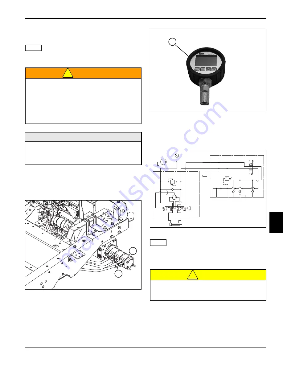
Steering Relief Valve Pressure Test

See Figures 7-4 through 7-6.

NOTE

Before performing this test, perform field test procedures. 
(See “Field Test Procedures” on page 6-23.
)

WARNING

1.

Operate hydraulic system until oil temperature is 
120–150° F (49–65° C).

2.

Park the mower safely. (See “Park Mower Safely” on 
page 1-6.)

Figure 7-4

3.

Disconnect hose (2) from fitting (1).

4.

Assemble test tee fitting to fitting (1).

5.

Secure hose (2) to test tee fitting.

Figure 7-5

6.

Connect test hose and pressure gauge (3) to test tee 
fitting.

7.

Bypass seat switch and engage park brake (park 
brake switch in the on position).

Figure 7-6: Steering Relief Valve Pressure Test

NOTE

Verify engine rpm is within specification (3000 rpm 

±

 50) 

to ensure accurate hydraulic test results.

8

.

Start engine and run at full throttle (3000 rpm ± 50).

CAUTION

9.

Turn the steering wheel fully right against stop.

10. Record pressure reading.

The hydraulic system is under pressure, and the 
oil will be hot.

• Always relieve pressure in the hydraulic 

system before performing service.

• Failure to follow appropriate safety 

precautions may result in death or serious 
injury.

Required Tools and Materials

• Pressure Gauge 4000 psi (276 bar)

• -6 ORFS Test Hose 4000 psi (276 bar)

• -6 ORFS Tee Fitting

2

1

MAR0175

Do not run lift/steering relief valve over relief 
longer than 10 seconds, or damage may occur to 
hydraulic system components.

TN1275

3

MAR0176

Summary of Contents for Jacobsen SLF530

Page 1: ...n this machine should be trained in its proper use warned of its dangers and should read the entire manual before attempting to set up operate adjust or service the machine 2018 Textron Specialty Vehicles TSV This manual may not re reproduced in whole or in part without the express permission of TSV Augusta Technical Communications Department ...

Page 2: ......

Page 3: ...or s manual and parts manual for specific information on these topics THE INFORMATION CONTAINED IN THIS MANUAL IS BASED ON MACHINES MANUFACTURED UP TO THE TIME OF PUBLICATION JACOBSEN RESERVES THE RIGHT TO CHANGE ANY OF THIS INFORMATION WITHOUT NOTICE California Proposition 65 Warning WARNING Trademark Acknowledgement Jacobsen acknowledges the following trademarks for company names or products men...

Page 4: ...cedures will require the use of specific tools and or materials These tools and or materials will be listed for reference prior to beginning a procedure Specifications Near the beginning of each chapter is a specifications listing This listing contains any specifications contained within the chapter Quick Reference Specifications A list of all machine specifications can be found in Chapter 2 Speci...

Page 5: ...3 4 5 6 7 8 Table of Contents 673831 Rev A 5 1 Safety Specifications and General Information Engine Electrical Hydrostatic Power Train Hydraulics Steering Cutting Units Accessories and Miscellaneous Repair ...

Page 6: ......

Page 7: ...ace Protection 1 6 Park Mower Safely 1 6 Use Lifting Equipment Safely 1 7 Support Machine Securely 1 7 Use Compressed Air and Air Tools Safely 1 7 Service Tires Safely 1 8 Handle Fuel Safely 1 8 Store Volatile and Hazardous Materials Safely 1 8 Handle Chemical Products Safely 1 9 Service Hydraulic System Safely 1 9 Service Cooling System Safely 1 9 Service Electrical Components Safely 1 10 Dispose...

Page 8: ...eginning service Prepare proper work space lighting A well lit work area can make the job easier Follow procedures and safety warnings Service procedures are written to be as safe and efficient as possible Never take shortcuts Be prepared for emergencies Accidents can happen even under the best conditions Fire extinguishers and first aid kits should be well maintained and easily accessible Safety ...

Page 9: ...SAFETY 673831 Rev A 1 3 1 Figure 1 1 MAR0230 1 2 2 3 4 5 6 7 8 9 10 10 10 11 12 13 14 15 ...

Page 10: ...1 4 673831 Rev A SAFETY 1 009034880 4181865 REV B 5 1 2 3 4 6 7 20 4262591 8 S 15 mg kg 4324674 9 4397486 10 11 ...

Page 11: ...SAFETY 673831 Rev A 1 5 1 3008682 838363 105dB LWA 12 1 37 1 72 bar 20 25 psi 4323911 13 14 15 ...

Page 12: ... protection when sparks and flying debris are present Vented Goggles Goggles offer side protection not offered by safety glasses alone Unvented Goggles Unvented goggles offer protection from chemical splashes and vapors Park Mower Safely See Figure 1 2 WARNING 1 Park the mower on a solid level surface 2 Remove feet from traction pedal Figure 1 2 3 Disengage mow switch 1 4 Lower the cutting units b...

Page 13: ...ction while using compressed air and air tools When using air tools do not exceed the air pressure rating for the tool When using an impact wrench always use approved impact sockets Never use standard sockets on an impact wrench Disconnect the air supply before changing air tool attachments Never point air nozzles or air tools at another person Always maintain air tools properly Always check the l...

Page 14: ...al state or federal ordinances and recommendations from your fuel supplier Never overfill or allow the tank to become empty Use clean fresh fuel Do not fill above the fuel filler neck Store Volatile and Hazardous Materials Safely Store volatile materials gasoline diesel fuel oil etc in approved containers that are clearly marked Containers should be stored in an approved safety cabinet away from p...

Page 15: ...with care Refer to the chemical manufacturer s Material Safety Data Sheet MSDS for information regarding health hazards safe handling and emergency response procedures The hydraulic system is under pressure and the oil may be hot Always allow the machine to cool completely before performing service Always relieve pressure in the hydraulic system before performing service Always use appropriate saf...

Page 16: ...th certain types of plastics Make sure the fluid to be stored is compatible with the storage container Never use food or beverage containers to store waste fluids IMPORTANT Dispose of waste fluids properly at approved local recycling centers If recycling facilities are not available contact your local community for the correct disposal procedure for waste fluids Dispose of old batteries properly B...

Page 17: ...wer Identification 2 2 Serial Number 2 2 Engine Serial Number 2 2 Optional Machine Accessories 2 2 Component Location 2 3 Specifications 2 4 Quick Reference Specifications 2 4 Standard Torque Values 2 10 Inch Fastener Torque Values 2 10 Metric Fastener Torque Values 2 10 ...

Page 18: ...n SLF530 Mower The second digit is the cutting unit configuration 5 Five 18 inch 457 mm cutting units three front and two rear The third digit is the seat option 1 Suspension Seat The fourth digit is the tire option 3 3WD Smooth Tires 5 4WD Smooth Tires Figure 2 3 Engine Serial Number The engine serial number 8 is located on a plate attached to the top of the rocker arm cover which also includes t...

Page 19: ...e components and correct operating procedures before beginning repair procedures 1 Seat 5 Left Front Reel 9 Right Rear Reel 13 Hydraulic Tank 2 Instrument Panel 6 Center Reel 10 Fuel Tank 14 Battery 3 Steering Wheel 7 Right Front Reel 11 Hood 4 Traction Pedal 8 Left Rear Reel 12 ROPS MAR0232 1 2 3 4 5 6 7 8 9 10 11 12 13 14 1 2 3 4 5 6 7 8 9 10 11 12 13 14 ...

Page 20: ...noid Coil at 68 F ohms 5 3 10 Resistance Across Solenoid Coil Parking Brake Solenoid Coil at 68 F ohms 10 3 10 Resistance Across Solenoid Coil 4WD Solenoid Coil at 68 F ohms 3 4 10 Resistance Across Fuel Shutoff Pull In Coil at 68 F ohms 0 5 10 Resistance Across Fuel Shutoff Hold In Coil at 68 F ohms 15 10 Mow Backlap Lift Lower Solenoids Nut Torque lb ft N m 10 13 6 Parking Brake Solenoid Nut Tor...

Page 21: ...aring Support Rotation Torque lb ft N m 8 85 30 12 30 Valving Cover Screws lb ft N m 61 10 83 10 Brake Housing Screws lb ft N m 107 10 145 10 Rear Wheel Motor s Rear Motor Screws lb ft N m 37 47 51 61 Test and Adjustment Specifications Front Reel Valve Pump Flow gpm lpm 5 2 19 8 at 3000 rpm Rear Reel Valve Pump Flow gpm lpm 5 2 19 8 at 3000 rpm Lift Steer Pump Flow gpm lpm 5 2 19 8 at 3000 rpm Hyd...

Page 22: ...lignment Toe In Measurement 4WD Option in mm 0 0625 1 6 Rear Axle Spindle Arm to Axle Stop Measurement 4WD Option in mm 0 0625 to 0 125 1 6 to 3 2 Repair Specifications Steering Wheel Nut lb ft N m 25 30 34 41 Steering Column to Steering Unit Screw Torque lb ft N m 15 20 Steering Cylinder to Steering Arm Torque 3WD Option lb ft N m 103 140 Steering Cylinder Ball Joint to Steering Arm Torque 4WD Op...

Page 23: ...rque lb ft N m 25 37 33 9 50 2 Bedknife Mounting Screw Torque lb in N m 90 120 10 2 13 6 Reel Bearing Housing Assembly Mounting Screw Torque lb ft N m 18 22 24 4 29 8 Front Roller Lock Nut Initial Torque lb in N m 10 30 13 6 40 7 Front Roller Rotational Torque lb in N m 3 7 0 3 0 8 Rear Roller Mounting Screw Torque lb ft N m 16 24 21 7 32 5 Rear Roller Lock Nut Initial Torque lb in N m 10 30 13 6 ...

Page 24: ...225 237 305 Engine Manufacturer Model Kubota Tier 4 D1105 E4B Engine Type 4 stroke diesel Fuel Requirement No 2 D diesel fuel Cetane Rating 45 Number of Cylinders Configuration 3 in line Displacement cu in cc 68 53 1 123 Bore x Stroke in mm 3 07 x 3 09 78 x 78 4 Power Output hp kW 24 8 18 5 3000 rpm Firing Order 1 2 3 Compression Ratio 24 1 Injection Timing Before T D C degrees 19 Cooling System l...

Page 25: ... Ground Clearance in mm TBD Turning Circle Curb to Curb outside tire to outside tire in Transport Left Turn in mm TBD Turning Circle Curb to Curb outside tire to outside tire in Transport Right Turn in mm TBD Uncut Turning Circle in mm TBD Weight Of SLF530 Machine With ROPS 3WD Option No Reels And Fuel Tank Empty lb kg TBD Weight Of SLF530 Machine With ROPS 4WD Option No Reels And Fuel Tank Empty ...

Page 26: ... 156 154 209 1 4 20 in lb Nm 75 8 4 100 11 3 107 12 1 143 16 1 9 16 18 ft lb Nm 92 124 122 165 129 174 172 233 1 4 28 in lb Nm 85 9 6 115 13 0 120 13 5 163 18 4 5 8 11 ft lb Nm 113 153 151 204 159 215 211 286 5 16 18 in lb Nm 157 17 7 210 23 7 220 24 8 305 34 4 5 8 18 ft lb Nm 128 173 170 230 180 244 240 325 5 16 24 in lb Nm 173 19 5 230 26 0 245 27 6 325 36 7 3 4 10 ft lb Nm 200 271 266 360 282 3...

Page 27: ... E4B 3 3 Checks and Adjustments 3 5 Purging the Fuel System 3 5 Repair 3 6 Fan Belt 3 6 Air Cleaner Assembly 3 6 Muffler and Exhaust Assembly 3 7 Radiator Hydraulic Oil Cooler Assembly 3 8 Thermostat 3 11 Fuel Filters 3 11 Fuel Pump 3 12 Remote Oil Filter 3 12 Engine 3 13 Engine Service 3 17 ...

Page 28: ...perating limitations and environmental factors hp kW 24 8 18 5 3000 rpm Torque Output lb ft N m 52 7 71 5 2200 rpm Firing Order 1 2 3 Compression Ratio 24 1 Injection Timing Before T D C 19 Cooling System Liquid Cooled Cooling System Capacity Engine Only qt L 1 5 1 4 Minimum Idle Speed No Load 1750 rpm Maximum Speed No Load 3000 rpm Engine Oil Capacity qt L 5 4 5 1 Engine Oil Type 10W30 API Classi...

Page 29: ...es 3 1 and 3 2 Figure 3 1 Component Location Engine Front 1 Muffler 5 Alternator 9 Fuel Pump 2 Exhaust Manifold 6 Fan Belt 10 Fuel Filter 3 Starter Motor 7 Thermostat 11 Engine Remote Oil Filter 4 Engine Oil Pressure Switch 8 Fuel Pre Filter MAR0240 1 2 3 4 5 6 7 8 9 10 11 ...

Page 30: ...v A ENGINE 3 Figure 3 2 Component Location Engine Rear Side 1 Fuel Shutoff Solenoid 5 Engine Temperature Sensor 2 Throttle Cable 6 Engine Oil Drain Plug 2 3 Air Vent Screw 4 Engine Oil Fill Cap MAR0241 1 2 3 4 5 6 6 ...

Page 31: ...ent screw 1 at the top of the filter by turning it counterclockwise two turns 4 Turn the ignition switch to the on position to allow the fuel pump to operate 5 When the bubbles disappear from fuel coming out of the air vent screw hole tighten air vent screw and turn ignition switch to the off position 6 Loosen the air vent screw 2 on the injection pump by turning it counterclockwise two turns WARN...

Page 32: ...n with a tension of 22 lb 98 N See engine manufacturer s manual for further information Air Cleaner Assembly Removal and Installation See Figure 3 5 CAUTION NOTE Air filter on this engine is a dry type never apply oil to this air filter 1 Park the mower safely See Park Mower Safely on page 1 6 2 Raise the hood Figure 3 5 NOTE Note the orientation of dust valve 2 before removing air filter dust cap...

Page 33: ... 5 and exhaust clamp 6 6 Disengage and remove tailpipe 7 7 Support muffler 12 and remove four screws 8 lock washers 9 flat washers 10 and nuts 11 8 Remove muffler 12 and gasket 13 9 Remove two nuts 14 and exhaust clamp 15 10 Support exhaust pipe 19 11 Remove two screws 16 lock washers 17 and nuts 18 12 Remove exhaust pipe 19 and gasket 20 Installation NOTE Install new gaskets during installation 1...

Page 34: ... containers that can hold up to 10 gal 37 8L when draining hydraulic oil 4 Drain engine cooling system 5 Drain hydraulic oil system See Hydraulic Oil Tank Drain Procedure on page 6 49 Figure 3 7 6 Open latches 1 and remove screen assembly 2 from radiator hydraulic oil cooler assembly 3 7 Remove two nuts 12 and bottom screen 13 Figure 3 8 NOTES Label all hoses before removing to ensure correct inst...

Page 35: ...nd fan 35 Figure 3 10 17 Remove two screws 40 flat washers 41 lock washers 42 and nuts 43 18 Remove three screws 44 lock washers 45 flat washers 46 and fan shroud 47 19 Remove two screws 48 lock washers 49 flat washers 50 and radiator shroud 51 20 Support the radiator hydraulic oil cooler 55 21 Remove three screws 52 lock washers 53 and flat washers 54 Lift radiator hydraulic oil cooler 55 off the...

Page 36: ... cap and start engine following instructions in Safety and Operation Manual CAUTION 10 Stop the engine and allow the radiator to cool 11 Fill expansion tank to cold mark on expansion tank 12 Check hydraulic oil level Add oil if needed Allow the engine coolant to completely cool before removing the expansion tank cap Hot coolant sprayed from the cap can cause serious personal injury ...

Page 37: ...e Figure 3 12 CAUTION 1 Park the mower safely See Park Mower Safely on page 1 6 2 Allow the engine to cool completely before servicing Figure 3 12 NOTES Label all hoses before removing to ensure correct installation 3 Loosen hose clamps 1 and disconnect hoses 2 and 3 from pre filter 4 4 Remove hardware 5 and pre filter clamp 6 Remove pre filter 4 5 Clean area around fuel filter cartridge 7 6 Remov...

Page 38: ... by reversing the order of removal Remote Oil Filter Removal and Installation See Figures 3 14 1 Park the mower safely See Park Mower Safely on page 1 6 2 Allow engine to cool completely 3 Raise the hood Figure 3 14 NOTES Label all hoses before removing to ensure correct installation 4 Disconnect filter inlet hose 1 and outlet hose 2 5 Remove oil filter cartridge 3 6 Remove two screws 4 lock washe...

Page 39: ...s on page 3 11 10 Remove fuel pump See Fuel Pump on page 3 12 11 Remove remote oil filter See Remote Oil Filter on page 3 12 12 Remove hydraulic gear pump See Gear Pump on page 6 49 13 Remove hydraulic traction pump See Traction Pump on page 5 40 Figure 3 15 NOTE Cover the opening on the intake manifold to prevent debris from entering the engine 14 Loosen hose clamp 1 and disconnect hose 2 from in...

Page 40: ...ressure switch wire 15 Figure 3 19 NOTE Label all wires before disconnecting to ensure correct installation Label all hoses before disconnecting to ensure correct installation 24 Remove nut and disconnect wire 16 from glow plug connector bar 25 Remove nut and disconnect wire 17 from coolant temperature sending unit 26 Disconnect wire connector 18 from fuel shutoff solenoid 27 Loosen hose clamp 19 ...

Page 41: ...nner while preventing damage to engine Installation Notes Inspect engine mounts and replace if necessary Install engine by reversing the order of removal Apply dielectric grease Jacobsen PN 365422 to any wire connectors disconnected Use new exhaust gasket when installing exhaust system Fill radiator with clean water and ethylene glycol based antifreeze mixed for coldest ambient temperature Replace...

Page 42: ... 45 Coupler Screw 3 7 Ground Cable 20 Flat Washer 33 Engine Mount 46 Lock Washer 3 8 Belt Guard Bolt 21 Side Engine Mount 34 Bell Housing 47 Coupler 9 Belt Guard 22 Mount Screw 2 35 M8 x 30 mm Screw 3 48 Temperature Sender 10 Exhaust Bracket 23 Lock Washer 2 36 Lock Washer 3 49 M6 x 55 mm Screw 11 Exhaust Bracket Screw 2 24 Flat Washer 2 37 Flat Washer 3 50 M6 x 50 mm Screw 12 Lock Washer 2 25 Eng...

Page 43: ...ers 40 and bell housing 41 13 Remove three screws 45 lock washers 46 and coupler 47 14 Remove engine temperature sender 48 15 Remove screw 49 screw 50 and throttle bracket 51 16 Inspect all parts for wear or damage Assembly Notes Assemble the engine by reversing the order of disassembly Apply Teflon tape to the threads of the engine temperature sensor 48 before installing Apply Loctite B275 to thr...

Page 44: ...3 18 673831 Rev A ENGINE 3 Page Intentionally Blank ...

Page 45: ... Circuit Schematic On Seat 4 22 Run Circuit Schematic Off Seat 4 24 Charging Circuit Theory of Operation 4 26 Charging Circuit Schematic 4 27 Mow Backlap Circuit Theory of Operation 4 29 Mow Backlap Circuit Schematic 4 30 Lift Lower Circuit Theory of Operation 4 33 Lift Lower Circuit Schematic 4 34 Optional Work Lights Circuit Theory of Operation 4 37 Optional Work Lights Circuit Schematic 4 38 In...

Page 46: ... 61 Fan Motor Test 4 61 Engine Temperature Sender Test 4 62 Repair 4 63 Battery 4 63 Instrument Panel 4 64 Rocker Switches 4 64 Lift Lower Joystick 4 65 Relays 4 65 Fuses 4 66 LDU 4 66 Key Switch 4 67 LDU Buzzer 4 67 Seat Switch 4 68 Neutral Proximity Switch 4 68 Lift Proximity Switch 4 69 Forward Proximity Switch 4 69 Fan Motor 4 70 Engine Oil Pressure Switch 4 70 Engine Temperature Sensor 4 71 F...

Page 47: ...8 F ohms 5 3 10 Resistance Across Solenoid Coil Lower Solenoid Coil at 68 F ohms 5 3 10 Resistance Across Solenoid Coil Lift Solenoid Coil at 68 F ohms 5 3 10 Resistance Across Solenoid Coil Parking Brake Solenoid Coil at 68 F ohms 10 3 10 Resistance Across Solenoid Coil 4WD Solenoid Coil at 68 F ohms 3 4 10 Resistance Across Fuel Shutoff Pull In Coil at 68 F ohms 0 5 10 Resistance Across Fuel Shu...

Page 48: ...many switch configurations Switches are designated by the number of poles circuits controlled and throws actuator positions Unless otherwise specified switches are shown in the Normally Open N O position Single Pole Single Throw SPST Double Pole Single Throw DPST Single Pole Double Throw SPDT Double Pole Double Throw DPDT Proximity Switch Switching Devices Temperature Switch Pressure Switch Relay ...

Page 49: ...s Electric Motors may also include AC or DC Stator Alternator Actuating Devices Solenoid Valve PTO Clutch Engine Related Devices Ignition Coil Spark Plug Regulator Fuel Shutoff Solenoid Lights Single Element Light Dual Element Light M G G U 3 U Pull In Hold In ...

Page 50: ...ure cabinet housing etc Wires crossing but not connected Ground to earth Wiring Connections Ground to chassis Coil Direct Current DC as shown on an oscilloscope Battery Alternating Current AC as shown on an oscilloscope Diode Resistor Pin and Socket Connector ...

Page 51: ...onnector Not used on this mower 2 1 CAN Resistor R3 Fan Motor M4 C B A MCU J5 U1 Brown 1 2 3 4 5 6 12 11 10 9 8 7 4WD Solenoid Diode D1 Engine Temp Resistor R2 Male Terminal 1 2 Fuel Pump M2 Alternator U4 1 Starter F M1 2 K1 F10 K3 F7 F4 K4 F8 F6 F5 F3 K2 F2 F9 85 87A 87 30 1 2 1 2 1 2 1 2 1 2 86 K5 85 87A 87 30 86 85 87A 87 30 86 85 87A 87 30 1 2 1 2 F1 1 2 1 2 1 2 86 87 87A 30 85 86 Air Ride Sea...

Page 52: ... Light Switch SW6 Black Side Shift Switch SW9 White Not used on this mower 7 8 4 1 5 2 6 3 Ignition Switch SW1 Joystick SW3 1 2 3 6 5 4 CAN Resistor R4 C B A Display U2 Main Harness J1 1 2 3 4 5 6 7 8 9 10 11 12 13 14 15 16 17 18 2 3 4 5 6 12 11 10 9 8 7 Terminal Identification is from open Not Wire end of connector ...

Page 53: ...mperature Sender See Figure 4 3 SOL1 Front Mow Solenoid See Figure 4 4 SOL2 Rear Mow Solenoid See Figure 4 4 SOL3 Front Backlap Solenoid See Figure 4 4 SOL4 Rear Backlap Solenoid See Figure 4 4 SOL5 Lower Solenoid See Figure 4 4 SOL6 Lift Solenoid See Figure 4 4 SOL7 4WD Solenoid See Figure 4 4 SOL8 Parking Brake Solenoid See Figure 4 4 SOL9 Weight Transfer Solenoid See Figure 4 4 SOL10 Left Side ...

Page 54: ...n 915 Ye F3 F2 F11 F1 F9 F6 F7 B1 MCU 1 06 Start K4 M4 K5 MCU 3 09 Ground MCU 6 09 Ground MCU 1 02 Ignition Run 105 Rd Og 20 Bk 20 Bk MCU 1 10 Ground 20 Bk MCU 1 07 Ground 20 Bk MCU 4 01 Seat Switch 119 Og Bn MCU 6 07 MCU 6 06 12V Unswitched MCU 6 01 Fuel Pull MCU 2 06 Fuel Hold 12V Unswitched MCU 1 04 MCU 1 01 12V Unswitched 12V Unswitched MCU 5 08 Glow Plug 121 Rd 121 Rd 103 Rd F8 MCU 3 02 Engin...

Page 55: ... Bu Ye MCU 6 05 Backlap 2 147 Bu Ye 20 Bk 147 Bu Ye SOL3 SOL4 2 3 4 6 1 J1 17 J1 18 J1 01 J1 02 J1 04 J1 03 J1 13 J1 12 128 Ye 111 Gy Wh 128 Ye J1 10 20 Bk 158 Og J1 08 125 Ye Rd 124 Ye Rd J1 11 5 147 Bn 147 Bn 147 Bn 146 Wh 146 Wh 146 Wh 6 Og 106 Og 1 3 4 5 2 Bu Bu 6 Bk Bk Bk 8 Ye 9 Gn 147 Bn 146 Wh 8 Ye 9 Gn 2 3 4 6 1 5 2 3 J2 1 J2 2 4 6 7 1 5 8 156 Og Gn 20 Bk 20 Bk 10 Ye Rd 10 Ye Rd 4 Rd Ye 20...

Page 56: ...amp fuse F17 output terminal to the ECU relay K15 terminals 30 and 86 Unswitched power is available from 30 amp fuse F18 output terminal to the power relay K12 terminal 30 Unswitched power is available from 35 amp fuse F19 output terminal to the starter relay K14 terminal 30 Unswitched power is available from 10 amp fuse F19 output terminal to the differential lock driver U9 terminal B Switched Po...

Page 57: ...ing brake switch in the on position and traction pedal in the Neutral position power is sent from MCU terminal 2 06 to the fuel solenoid SOL12 hold in coil terminal B and the engine can start when the key switch is turned to the Start position CAN Diagnostic Circuit Blue With the MCU and LDU energized a CAN signal is supplied from MCU terminals 1 09 High and 1 08 Low to the following LDU terminals...

Page 58: ...915 Ye 914 Gn 915 Ye 914 Gn 915 Ye F3 F2 F1 F9 F6 F7 MCU 1 06 Start K4 M4 K5 MCU 3 09 Ground MCU 6 09 Ground MCU 1 02 Ignition Run 105 Rd Og 20 Bk 20 Bk MCU 1 10 Ground 20 Bk MCU 1 07 Ground 20 Bk MCU 4 01 Seat Switch 119 Og Bn MCU 6 07 MCU 6 06 12V Unswitched MCU 6 01 Fuel Pull MCU 2 06 Fuel Hold 12V Unswitched MCU 1 04 MCU 1 01 12V Unswitched 12V Unswitched MCU 5 08 Glow Plug 121 Rd 121 Rd 103 R...

Page 59: ...J1 18 J1 01 J1 02 J1 04 J1 03 J1 13 J1 12 128 Ye 111 Gy Wh 128 Ye J1 10 20 Bk J1 08 J1 11 5 147 Bn 147 Bn 147 Bn 146 Wh 146 Wh 146 Wh 6 Og 106 Og 1 3 4 5 2 Bu Bu 6 Bk Bk Bk 8 Ye 9 Gn 147 Bn 146 Wh 8 Ye 9 Gn 2 3 4 6 1 5 2 3 4 6 7 1 5 8 156 Og Gn 20 Bk 20 Bk 10 Ye Rd 10 Ye Rd 4 Rd Ye 20 Bk 6 Og 114 Gn 115 Ye 130 Bu 10 Ye Rd 6 Og 6 Og 2 3 6 Og 5 Og 6 4 2 5 3 1 13 WRd Og 4 Rd Ye 4 Rd Ye 105 Rd Og 106 ...

Page 60: ...4 16 673831 Rev A ELECTRICAL 4 Page Intentionally Blank ...

Page 61: ...the on position and traction pedal in the Neutral position power is sent from MCU terminal 2 06 to the fuel solenoid SOL12 hold in coil terminal H and the engine can start when the keyswitch is turned to the Start position Glow Plug Circuit When the key switch is turned to the run position voltage is sent from key switch terminal 2 to MCU U1 terminal 4 07 The MCU sends switched power from terminal...

Page 62: ...tral Switch 106 Og 116 Wh Ye 106 Og G 3 U 86 85 30 87 U4 Rd Rd 106 Og 20 Bk 3 Rd 105 Rd Og 20 Bk 20 Bk 914 Gn 915 Ye 914 Gn 915 Ye 914 Gn 915 Ye 914 Gn 915 Ye F3 F2 F9 F6 F7 MCU 1 06 Start MCU 3 09 Ground MCU 6 09 Ground MCU 1 02 Ignition Run 105 Rd Og 20 Bk 20 Bk MCU 1 10 Ground 20 Bk MCU 1 07 Ground 20 Bk MCU 4 01 Seat Switch 119 Og Bn MCU 6 07 MCU 6 06 12V Unswitched MCU 6 01 Fuel Pull MCU 2 06...

Page 63: ...7 Start 113 Rd Og 105 Rd Og 106 Og 1 Rd 914 Gn 915 Ye 914 Gn 915 Ye 114 Gn 115 Ye 115 Ye 114 Gn 115 Ye 114 Gn J1 01 J1 02 J1 04 J1 03 128 Ye 128 Ye J1 10 20 Bk J1 08 J1 11 2 3 4 6 1 5 2 3 4 6 7 1 5 8 156 Og Gn 20 Bk 10 Ye Rd 10 Ye Rd 4 Rd Ye 20 Bk 6 Og 114 Gn 115 Ye 130 Bu 10 Ye Rd 6 Og 6 Og 5 Og 6 4 2 5 3 1 13 WRd Og 4 Rd Ye 4 Rd Ye 105 Rd Og 106 Og 1 Rd F4 4 Rd Ye 113 Rd Og 13 Rd Og 5 Og 6 Og U2...

Page 64: ...4 20 673831 Rev A ELECTRICAL 4 Page Intentionally Blank ...

Page 65: ... energize With switched power provided to the fuel pump the fuel pump starts to operate With switched power provided to the LDU the LDU display will energize and will display vehicle status Run Circuit On Seat The seat switch allows the engine to continue to operate when the parking brake switch is in the off position traction pedal is not in neutral position or when the mow switch is in the on po...

Page 66: ...6 Og 20 Bk 3 Rd 105 Rd Og 914 Gn 915 Ye 914 Gn 915 Ye 914 Gn 915 Ye 914 Gn 915 Ye F3 F6 F7 MCU 1 06 Start MCU 3 09 Ground MCU 6 09 Ground MCU 1 02 Ignition Run 105 Rd Og 20 Bk 20 Bk MCU 1 10 Ground 20 Bk MCU 1 07 Ground 20 Bk MCU 4 01 Seat Switch 119 Og Bn MCU 6 07 MCU 6 06 12V Unswitched MCU 6 01 Fuel Pull MCU 2 06 Fuel Hold 12V Unswitched MCU 1 04 MCU 1 01 12V Unswitched 12V Unswitched MCU 5 08 ...

Page 67: ...106 Og 1 Rd 914 Gn 915 Ye 914 Gn 915 Ye 114 Gn 115 Ye 115 Ye 114 Gn 115 Ye 114 Gn J1 01 J1 04 J1 03 128 Ye 128 Ye J1 10 20 Bk J1 08 J1 11 2 3 4 6 1 5 2 3 4 6 7 1 5 8 156 Og Gn 20 Bk 10 Ye Rd 10 Ye Rd 4 Rd Ye 20 Bk 6 Og 114 Gn 115 Ye 130 Bu 10 Ye Rd 6 Og 6 Og 5 Og 6 4 2 5 3 1 4 Rd Ye 4 Rd Ye 105 Rd Og 106 Og 1 Rd F4 4 Rd Ye 5 Og 6 Og U2 LDU 1 01 12V LDU 1 02 Ground LDU 1 03 Wake Up LDU 1 04 LDU 1 0...

Page 68: ... 914 Gn 915 Ye 914 Gn 915 Ye 914 Gn 915 Ye 914 Gn 915 Ye F3 F6 F7 MCU 1 06 Start MCU 3 09 Ground MCU 6 09 Ground MCU 1 02 Ignition Run 105 Rd Og 20 Bk 20 Bk MCU 1 10 Ground 20 Bk MCU 1 07 Ground 20 Bk MCU 4 01 Seat Switch 119 Og Bn MCU 6 07 MCU 6 06 12V Unswitched MCU 6 01 Fuel Pull MCU 2 06 Fuel Hold 12V Unswitched MCU 1 04 MCU 1 01 12V Unswitched 12V Unswitched MCU 5 08 Glow Plug 121 Rd 121 Rd 1...

Page 69: ...Og 106 Og 1 Rd 914 Gn 915 Ye 914 Gn 915 Ye 114 Gn 115 Ye 115 Ye 114 Gn 115 Ye 114 Gn J1 01 J1 02 J1 04 J1 03 128 Ye 128 Ye J1 10 20 Bk J1 08 J1 11 2 3 4 6 1 5 2 3 4 6 7 1 5 8 156 Og Gn 20 Bk 10 Ye Rd 10 Ye Rd 4 Rd Ye 20 Bk 6 Og 114 Gn 115 Ye 130 Bu 10 Ye Rd 6 Og 6 Og 5 Og 6 4 2 5 3 1 4 Rd Ye 4 Rd Ye 105 Rd Og 106 Og 1 Rd F4 4 Rd Ye 5 Og 6 Og U2 LDU 1 01 12V LDU 1 02 Ground LDU 1 03 Wake Up LDU 1 0...

Page 70: ...terminal 1 01 Charging Circuit When the key switch SW1 is turned to the run position voltage is provided from key switch terminal 4 to the ignition relay K1 terminal 86 energizing the relay With the relay energized switched power is provided from ignition relay terminal 87 to the alternator field terminal exciting the alternator With the engine running and the alternator field terminal excited the...

Page 71: ...09 Ground MCU 1 02 Ignition Run 105 Rd Og 20 Bk 20 Bk MCU 1 10 Ground 20 Bk MCU 1 07 Ground 20 Bk MCU 4 01 Seat Switch MCU 6 07 MCU 6 06 12V Unswitched MCU 6 01 Fuel Pull MCU 2 06 Fuel Hold 12V Unswitched MCU 1 04 MCU 1 01 12V Unswitched 12V Unswitched MCU 5 08 Glow Plug MCU 3 02 Engine Temp 137 Pu J4 B J4 A R3 MCU 4 02 Crosscut Switch MCU 2 04 Fan Relay Unswitched power circuit Switched power cir...

Page 72: ...4 28 673831 Rev A ELECTRICAL 4 Page Intentionally Blank ...

Page 73: ... When the mow speed lever is placed in the MOW position the mow speed proximity switch SW12 is activated With the switch activated voltage is provided to MCU terminal 4 09 When the reels are lowered the center lift arm is brought near the magnetic target zone of the lift proximity switch SW8 activating the switch With the switch activated voltage is provided from the proximity switch to MCU U1 ter...

Page 74: ... 914 Gn 915 Ye 914 Gn 915 Ye 914 Gn 915 Ye 914 Gn 915 Ye F3 F6 F7 MCU 1 06 Start MCU 3 09 Ground MCU 6 09 Ground MCU 1 02 Ignition Run 105 Rd Og 20 Bk 20 Bk MCU 1 10 Ground 20 Bk MCU 1 07 Ground 20 Bk MCU 4 01 Seat Switch MCU 6 07 MCU 6 06 12V Unswitched MCU 6 01 Fuel Pull MCU 2 06 Fuel Hold 12V Unswitched MCU 1 04 MCU 1 01 12V Unswitched 12V Unswitched MCU 5 08 Glow Plug 121 Rd 121 Rd 103 Rd MCU ...

Page 75: ...art 105 Rd Og 106 Og 1 Rd 914 Gn 915 Ye 914 Gn 915 Ye 114 Gn 115 Ye 115 Ye 114 Gn 115 Ye 114 Gn 20 Bk 20 Bk 147 Bu Ye SOL3 SOL4 J1 01 J1 02 J1 04 J1 03 20 Bk J1 08 J1 11 2 3 4 6 7 1 5 8 20 Bk 10 Ye Rd 10 Ye Rd 4 Rd Ye 20 Bk 6 Og 114 Gn 115 Ye 130 Bu 10 Ye Rd 6 Og 5 Og 6 4 2 5 3 1 4 Rd Ye 4 Rd Ye 105 Rd Og 106 Og 1 Rd F4 4 Rd Ye 5 Og 6 Og U2 LDU 1 01 12V LDU 1 02 Ground LDU 1 03 Wake Up LDU 1 04 LD...

Page 76: ...4 32 673831 Rev A ELECTRICAL 4 Page Intentionally Blank ...

Page 77: ... vehicle status Lift Lower Modes The one touch or manual lift lower modes are activated using the menus on the LDU The selected mode is communicated to the MCU by the CAN circuit Manual Mode When One Touch is disabled the cutting units will lift or lower only while the lift lower joystick is pulled or pushed One Touch Mode With One Touch enabled and the mow switch is in the ON position push and re...

Page 78: ...Bk 3 Rd 105 Rd Og 914 Gn 915 Ye 914 Gn 915 Ye 914 Gn 915 Ye 914 Gn 915 Ye F3 F6 F7 MCU 1 06 Start MCU 3 09 Ground MCU 6 09 Ground MCU 1 02 Ignition Run 105 Rd Og 20 Bk 20 Bk MCU 1 10 Ground 20 Bk MCU 1 07 Ground 20 Bk MCU 4 01 Seat Switch MCU 6 07 MCU 6 06 12V Unswitched MCU 6 01 Fuel Pull MCU 2 06 Fuel Hold 12V Unswitched MCU 1 04 MCU 1 01 12V Unswitched 12V Unswitched MCU 5 08 Glow Plug 121 Rd 1...

Page 79: ...p LDU 1 04 LDU 1 05 LDU 1 06 CAN L CAN H LDU 1 07 LDU 1 08 LDU 1 09 LDU 1 10 LDU 1 11 Buzzer LDU 1 12 J1 5 J1 6 J5 B J5 A R4 20 Bk 1 2 U2 130 Bu 4 Rd Ye Unswitched power circuit Switched power circuit Lift circuit Lower circuit CAN Circuit Grounds 20 Bk 157 Bu Wh SOL5 20 Bk 108 Ye SOL6 20 Bk 157 Bu Wh SOL13 20 Bk 108 Ye SOL14 U1 MCU 2 01 Lower Solenoid MCU 2 03 Lift Solenoid MCU 2 05 Parking Brake...

Page 80: ...4 36 673831 Rev A ELECTRICAL 4 Page Intentionally Blank ...

Page 81: ...r is available from 15 amp fuse F4 output terminal to the following components Ignition switch terminal 6 LDU Display terminal 1 01 Switched Power Circuit Green When the key switch SW1 is turned to the run position voltage is provided from key switch terminal 4 to ignition relay K1 terminal 86 energizing the relay and to MCU U1 terminal 1 02 With the ignition relay K1 energized switched power is p...

Page 82: ...s Circuit Schematic See Figures 4 18 and 4 19 Figure 4 18 MAR0020 Rd Bk F11 B1 Unswitched power circuit Switched power circuit Work light circuit CAN Circuit Grounds 86 85 30 87 87A 106 Og K1 1 Rd 1 Rd 1 Rd 106 Og 20 Bk 3 Rd 105 Rd Og F3 105 Rd Og 1 Rd ...

Page 83: ... L1 105 Rd Og 106 Og 1 Rd J1 01 J1 04 J1 03 2 3 6 Og 5 Og 6 4 2 5 3 1 4 Rd Ye 4 Rd Ye 105 Rd Og 106 Og 1 Rd F4 4 Rd Ye 5 Og 6 Og 4 Rd Ye Unswitched power circuit Switched power circuit Work light circuit CAN Circuit Grounds 158 Og J1 14 157 Bu Gn 20 Bk Bk Bk Bu Ye Bu Ye Bk Bu Ye Bk Bu Ye J2 1 J2 2 1 2 L2 1 2 L3 ...

Page 84: ...4 40 673831 Rev A ELECTRICAL 4 Page Intentionally Blank ...

Page 85: ...ine temperature sensor R5 resistance changes in relationship to the engine coolant temperature As the engine temperature sensor is heated the resistance of the sensor changes from a high resistance to a low resistance The amount of resistance in the circuit is used by the MCU as a temperature measurement When the engine temperature reaches 150 F 66 C the MCU will send power from terminal 2 04 to t...

Page 86: ...4 Gn 915 Ye 914 Gn 915 Ye 914 Gn 915 Ye 914 Gn 915 Ye F3 F6 F7 MCU 1 06 Start K4 M4 K5 MCU 3 09 Ground MCU 6 09 Ground MCU 1 02 Ignition Run 105 Rd Og 20 Bk 20 Bk MCU 1 10 Ground 20 Bk MCU 1 07 Ground 20 Bk MCU 4 01 Seat Switch MCU 6 07 MCU 6 06 12V Unswitched MCU 6 01 Fuel Pull MCU 2 06 Fuel Hold 12V Unswitched MCU 1 04 MCU 1 01 12V Unswitched 12V Unswitched MCU 5 08 Glow Plug 121 Rd 121 Rd 103 R...

Page 87: ...e MCU 5 10 Lower MCU 4 11 Shift Left MCU 4 12 Shift Right MCU 4 07 Start 105 Rd Og 106 Og 1 Rd 914 Gn 915 Ye 914 Gn 915 Ye 114 Gn 115 Ye 115 Ye 114 Gn 115 Ye 114 Gn J1 01 J1 04 J1 03 128 Ye 111 Gy Wh 128 Ye J1 10 20 Bk J1 08 2 3 4 6 1 5 156 Og Gn 4 Rd Ye 20 Bk 6 Og 114 Gn 115 Ye 130 Bu 6 Og 5 Og 6 4 2 5 3 1 4 Rd Ye 4 Rd Ye 105 Rd Og 106 Og 1 Rd F4 4 Rd Ye 5 Og 6 Og SW11 U2 LDU 1 01 12V LDU 1 02 Gr...

Page 88: ... associated input and output circuits are disabled in the MCU The unused circuits are Weight Transfer Solenoid SOL9 MCU 2 12 Left Deck Offset Solenoid SOL 10 MCU 6 02 Right Deck Offset Solenoid SOL11 MCU 5 05 Lower Solenoid 2 SOL13 Lift Solenoid 2 SOL14 Weight Transfer Solenoid 2 SOL15 MCU 2 12 Deck Offset Switch SW9 MCU 4 11 and 4 12 ...

Page 89: ...ft Sideshift MCU 5 05 Right Sideshift MCU 5 11 Lift MCU 4 09 Mow Sw MCU 4 08 Parking Brake MCU 6 11 Oil Pressure MCU 5 10 Lower MCU 4 11 Shift Left 142 Wh MCU 4 12 Shift Right 143 Bn 142 Wh 143 Bn MCU 4 07 Start 105 Rd Og 106 Og 1 Rd 2 3 4 6 1 J1 17 J1 18 J1 01 J1 04 J1 03 5 147 Bn 147 Bn 147 Bn 146 Wh 146 Wh 146 Wh 6 Og 106 Og 1 3 4 5 2 Bu Bu 6 Bk Bk Bk 8 Ye 9 Gn 147 Bn 146 Wh 5 Og 6 4 2 5 3 1 4 ...

Page 90: ...ow switch SW2 is in the ON position Place the mow switch SW2 in the OFF position Traction pedal not in neutral position Return traction pedal to Neutral position Remove foot from traction pedal Faulty relay power circuit Check continuity between 30 amp fuse F9 and starter relay K3 terminal 30 Continuity must be indicated Faulty starter relay K2 coil circuit Check continuity between the MCU termina...

Page 91: ...e Relays Test on page 4 53 Probable Cause Remedy Faulty seat switch Test seat switch SW4 See Seat Switch Test on page 4 54 Faulty seat switch circuit Check continuity between seat switch SW4 terminal 2 and MCU U1 terminal 4 01 Probable Cause Remedy Faulty alternator output circuit Make sure alternator output cable starter cable and battery positive cable terminals are clean and tight Check continu...

Page 92: ...ove 230 F 110 C Allow the engine to cool and check the engine cooling system Faulty lift proximity switch Test the lift proximity switch SW8 See Proximity Switches Test on page 4 57 Faulty parking brake switch Test the parking brake switch SW5 See Parking Brake Switch Test on page 4 56 Faulty neutral switch Test the neutral switch SW7 See Proximity Switches Test on page 4 57 Faulty front and rear ...

Page 93: ... overheat condition Lift solenoid SOL6 will not energize if the engine temperature is above 230 F 110 C Allow the engine to cool and check the engine cooling system Faulty lift lower joystick Test the lift lower joystick SW3 See Lift Lower Joystick Test on page 4 58 Faulty lower solenoid Test the lower solenoid SOL6 See Solenoids Test on page 4 59 Faulty wire harness Measure continuity between the...

Page 94: ...ition relay K1 terminal 87 and 10 amp fuse F8 Continuity must be indicated Check continuity between 10 amp fuse F8 and fan relay K4 terminal 30 Continuity must be indicated Check continuity between 30 amp fuse F5 and fan motor M4 terminal 1 Continuity must be indicated Check continuity between MCU U1 terminal 2 04 and fan relay K4 terminal 86 Continuity must be indicated Check continuity between f...

Page 95: ...le Cause Remedy Faulty engine temperature sensor Test the temperature sender R5 See Engine Temperature Sender Test on page 4 62 Faulty engine temperature circuit Check continuity between MCU U1 terminal 3 02 and the engine temperature sensor R5 terminal Continuity must be indicated ...

Page 96: ...e meter Operator s Manual for more information 2 If using a multimeter set to read ohms or set meter to continuity setting 3 Disconnect the ends of the wire being tested 4 Touch meter leads to the ends of the wire or to the terminals of the component to be tested Does meter read less than 0 5 ohm and or does the buzzer sound YES The wire is good NO Proceed to step 5 5 Use a known good jumper wire ...

Page 97: ...her test lead to terminal 3 and check for continuity Is continuity indicated YES Proceed to step 5 NO The relay is faulty replace the relay 5 Connect one test lead to terminal 1 6 Connect the other test lead to terminal 4 7 Connect a 12 volt DC power source to terminals 2 and 5 8 Check for continuity across terminals 4 and 1 Is continuity indicated YES The relay is good NO The relay is faulty repl...

Page 98: ...switch to the START position Check continuity between terminal 1 and terminals 2 4 and 5 Is continuity indicated YES The key switch is good NO The key switch is faulty replace the switch Seat Switch Test See Figure 4 26 1 Park the mower safely See Park Mower Safely on page 1 6 Figure 4 26 2 Connect test leads to the switch terminals 1 and 2 3 Check for continuity Is continuity indicated YES The sw...

Page 99: ...tch 13 Connect test leads to the switch terminals 4 and 5 14 Place the switch in the OFF position 15 Check for continuity Is continuity indicated YES Proceed to step 16 NO The switch is faulty replace the switch 16 Place the switch in the ON position 17 Check for continuity Is continuity indicated YES The switch is faulty replace the switch NO Proceed to step 18 18 Connect test leads to the switch...

Page 100: ...11 Place the switch in the On position 12 Check for continuity Is continuity indicated YES Proceed to step 13 NO The switch is faulty replace the switch 13 Connect test leads to the switch terminals 4 and 5 14 Place the switch in the OFF Locked position 15 Check for continuity Is continuity indicated YES Proceed to step 16 NO The switch is faulty replace the switch 16 Place the switch in the ON po...

Page 101: ...ximity Switch The proximity switch is a solid state switch and will have approximately a 2 to 3 volt drop across the switch when activated The switch must be tested with the switch plugged into the main harness and the key switch in the RUN position The switch may have to be removed from the mounting bracket to properly test the switch Figure 4 30 2 Confirm that 12 volts DC is present at terminal ...

Page 102: ...d hold the joystick in the lift position 7 Check for continuity Is continuity indicated YES Proceed to step 8 NO The joystick is faulty replace the joystick 8 Place the joystick in the center position 9 Connect test leads to the switch terminals 1 and 5 10 Check for continuity Is continuity indicated YES The joystick is faulty replace the joystick NO Proceed to step 11 11 Move the joystick to the ...

Page 103: ...rough the component match the specified value listed YES The solenoid is good NO The solenoid is faulty replace the solenoid Fuel Solenoid Test See Figure 4 33 1 Park the mower safely See Park Mower Safely on page 1 6 2 Disconnect the fuel solenoid wire connector Figure 4 33 3 Set the meter to read ohms 4 Measure the resistance between hold in terminal 1 and ground 3 Is the resistance value approx...

Page 104: ...replace the resistor Diode Test See Figure 4 35 1 Park the mower safely See Park Mower Safely on page 1 6 2 Remove diode Figure 4 35 3 Using a multimeter or ohmmeter check for continuity between terminals 1 and 2 Reverse the lead wires and check for continuity again Is continuity indicated in one direction and not in the other direction YES The diode is good NO The diode is faulty replace the diod...

Page 105: ...p is faulty replace the fuel pump Fan Motor Test See Figure 4 37 1 Park the mower safely See Park Mower Safely on page 1 6 2 Allow engine to cool completely Figure 4 37 NOTE Label all wires before disconnecting to ensure correct installation 3 Disconnect the fan motor harness connector 5 from the mower harness 4 Using a jumper wire connect the battery positive terminal to fan motor terminal 1 and ...

Page 106: ...dy 2 Is the temperature sender resistance approximately 943 ohms YES Continue with step 8 NO The engine temperature sender is faulty replace the engine temperature sender 7 Heat the oil to 280 F 138 C 8 Measure the resistance between the temperature sender terminal 1 and the sender body 2 Is the engine temperature sender resistance approximately 34 ohms YES The engine temperature sender is good NO...

Page 107: ...d remove the battery 12 NOTICE NOTES Install the battery by reversing the order of removal Route battery cables between the battery and battery tray to avoid pinch points Battery posts terminals and related accessories contain lead and lead compounds Wash your hands after handling Always wear eye protection when servicing battery Always disconnect the negative terminal first and positive terminal ...

Page 108: ...nstrument panel 3 up to clear the edge of the armrest 4 5 Disconnect the armrest harness 5 from instrument panel components 6 Lift and move the instrument panel aside or service components as needed Installation Notes Install the instrument panel by reversing the order of removal Rocker Switches This procedure applies to the following rocker switches Mow Switch 1 Parking Brake Switch 2 Optional Li...

Page 109: ...ower harness 5 Remove four screws 2 and flat washers 3 6 Remove the lift lower joystick 4 Installation Note Install joystick by reversing the order of removal Relays See Figure 4 44 NOTE This procedure applies to the following relays Ignition Relay 1 Glow Plug Relay 2 Starter Relay 3 Fan Relay 4 4WD Relay 5 Removal and Installation 1 Park the mower safely See Park Mower Safely on page 1 6 2 Discon...

Page 110: ...tall the fuse by reversing the order of removal LDU Removal and Installation See Figure 4 46 1 Park the mower safely See Park Mower Safely on page 1 6 2 Disconnect the negative battery cable at the battery 3 Remove the instrument panel Figure 4 46 4 Disconnect 12 pin harness connector from the LDU 5 Press tabs 1 on both sides of the LDU 2 and remove the LDU from the instrument panel Installation N...

Page 111: ...the key switch 2 7 Remove the key switch 2 Installation Note Adjust backing nut for proper switch height if necessary Install the key switch by reversing the order of removal LDU Buzzer Removal and Installation See Figure 4 48 1 Park the mower safely See Park Mower Safely on page 1 6 2 Disconnect the battery negative cable at the battery 3 Remove instrument panel See Instrument Panel on page 4 64 ...

Page 112: ...ottom of the seat Installation Notes Install the seat switch by reversing the order of removal Neutral Proximity Switch Removal and Installation See Figure 4 50 1 Park the mower safely See Park Mower Safely on page 1 6 2 Open the hood 3 Disconnect the negative battery cable at the battery Figure 4 50 NOTE Label all wires before disconnecting to ensure correct installation 4 Disconnect harness conn...

Page 113: ...roximity switch 5 Installation Notes Install the lift proximity switch by reversing the order of removal Forward Proximity Switch Removal and Installation See Figure 4 52 1 Park the mower safely See Park Mower Safely on page 1 6 2 Disconnect the negative battery cable at the battery Figure 4 52 NOTES Operator platform not shown for clarity Label all wires before disconnecting to ensure correct ins...

Page 114: ...n Notes Install the radiator fan by reversing the order of removal Engine Oil Pressure Switch Removal and Installation See Figure 4 54 CAUTION 1 Park the mower safely See Park Mower Safely on page 1 6 2 Raise the hood 3 Disconnect the negative battery cable at the battery Figure 4 54 NOTE Label all wires before disconnecting to ensure correct installation 4 Remove screw 3 and disconnect wire 2 fro...

Page 115: ...order of removal Apply Teflon tape to the threads of the engine temperature sensor before installing Fuel Solenoid Removal and Installation See Figure 4 56 1 Park the mower safely See Park Mower Safely on page 1 6 2 Raise the hood 3 Disconnect the negative battery cable at the battery Figure 4 56 NOTE Label all wires before disconnecting to ensure correct installation 4 Disconnect wire connector 1...

Page 116: ...acklap Solenoid 3 Rear Backlap Solenoid 4 The front mow and backlap solenoid coils are located on the front reel valve 7 under the operator platform The rear mow and backlap solenoid coils are located on the rear reel valve 8 under the operator platform Removal and Installation See Figure 4 58 1 Park the mower safely See Park Mower Safely on page 1 6 2 Disconnect the negative battery cable at the ...

Page 117: ... and apply dielectric grease Jacobsen PN 365422 to solenoid coil before installation Install the solenoid by reversing the order of removal Tighten nut 5 to 10 lb ft 13 6 N m 4WD Solenoid Coil Removal and Installation See Figure 4 60 1 Park the mower safely See Park Mower Safely on page 1 6 2 Disconnect the negative battery cable at the battery 3 Locate the 4WD valve 2 under the seat Figure 4 60 L...

Page 118: ...s or surface rust and apply dielectric grease Jacobsen PN 365422 to solenoid coil before installation Install the solenoid by reversing the order of removal Tighten nut 3 to 2 5 lb ft 3 4 N m MCU Removal and Installation See Figure 4 62 1 Park the mower safely See Park Mower Safely on page 1 6 2 Remove the floor access panel from the operator platform See Operator Platform on page 9 10 3 Disconnec...

Page 119: ...o ensure correct installation 4 Disconnect alternator cable 1 and wire connector 2 5 Loosen screw 8 and push the alternator 3 toward the engine 6 Remove fan drive belt 9 from alternator pulley 7 Support the alternator 3 8 Remove screw 8 lock washer 7 and flat washer 6 9 Remove screw 5 and nut 4 10 Remove alternator 3 Installation Notes Install the alternator by reversing the order of removal Adjus...

Page 120: ...ulator 12 7 Remove four screws 13 securing stator leads to rectifier 14 Lift rectifier off alternator 8 Remove two screws 15 and two nuts 16 9 Press on pulley end of rotor 20 to separate the alternator frame NOTES Use caution not to damage slip ring assembly on the brush end of rotor shaft when pressing rotor out of end frame Only press on the metal part of rotor shaft 10 Press rotor 20 out of end...

Page 121: ...ted YES Stator is bad Replace stator and drive frame end NO Stator is good Alternator Rotor Inspection Figure 4 66 Rotor Inspection 1 Measure the resistance across top slip ring 1 and bottom slip ring 2 Is the resistance approximately 2 9 ohms YES Continue with Step 2 NO Rotor is bad Replace the rotor 2 Check for continuity between the slip rings 1 and 2 and the rotor core 3 Is continuity indicate...

Page 122: ... for continuity between mounting holes 3 and the four stator lead posts 2 Reverse the tester leads and check for continuity again Is continuity indicated in one direction and not the other YES The rectifier is good NO One or more negative bridge diodes are bad Replace the rectifier Alternator Voltage Regulator Inspection Figure 4 69 Voltage Regulator Inspection 1 Check for continuity between B ter...

Page 123: ...tor 1 6 Support the starter motor 1 7 Remove screws 2 8 Remove starter motor Installation Note Install the starter motor by reversing the order of removal Starter Disassembly and Assembly NOTE If the starter screws or nuts have rust or other corrosion spray hardware with a rust penetrating fluid Figure 4 71 Diesel Starter Disassembly 1 2 3 4 5 MAR0043 MAR0222 1 2 3 4 5 6 7 8 9 10 10 11 12 13 14 15...

Page 124: ...remove the two brush holder brushes 2 from brush brackets 4 2 Measure the length 3 of the brushes attached to the brush holder Is the length less than 0 413 in 10 5 mm YES Brushes have too much wear Replace the brush holder assembly NO Continue with step 3 3 Check for continuity between the brush brackets 4 and the metal support plate 5 Is continuity indicated YES Brush holder is bad Replace the b...

Page 125: ... YES Correct the mica undercut with a saw blade and chamfer the segment edges The saw blade must be kept parallel with the armature shaft NO Continue with step 4 4 Check for continuity across the commutator segments 4 and the armature coil core 5 Is continuity indicated YES The armature is bad Replace the armature NO Continue with step 5 5 Check for continuity across the segments of the commutator...

Page 126: ...4 82 673831 Rev A ELECTRICAL 4 Page Intentionally Blank ...

Page 127: ...cuit Schematics 5 8 Traction Circuit Neutral Schematic and Theory of Operation 5 8 Traction Circuit 3WD Neutral Schematic 5 9 Traction Circuit 2WD 4WD Neutral Schematic 5 10 Traction Circuit Forward Schematic and Theory of Operation 5 12 Traction Circuit Forward 3WD Schematic 5 13 Traction Circuit Forward 2WD 4WD Schematic 5 14 Traction Circuit Reverse Schematic and Theory of Operation 5 16 Tracti...

Page 128: ...st Overview 5 25 Charge Pressure Test 5 25 Charge Pump Test 5 26 Flow Lock Tool 5 27 Traction System Test 5 28 Traction Pump Tests 5 29 3WD System Test 5 31 4WD System Test 5 35 Repair 5 40 Traction Pump 5 40 4WD Valve 5 45 Front Wheel Motor 5 47 Rear Wheel Motor 5 60 Traction Linkage 5 68 ...

Page 129: ...on Traction Pump Charge Relief Valve Plug lb ft N m 60 150 81 203 End Cap Screws lb ft N m 40 54 Loop Flushing Valve Plug lb ft N m 33 45 Neutral Return Seal Nut lb ft N m 16 22 Bypass Valve lb ft N m 15 20 High Pressure Relief Valves lb ft N m 60 81 Trunnion Cover Screw lb ft N m 24 33 4WD Valve 4WD Solenoid Valve lb ft N m 40 54 Check Valves lb ft N m 40 54 Hollow Plug lb ft N m 12 16 Gauge Port...

Page 130: ... twist hold the hose in a normal straight position When installing hoses place fittings at angles to avoid contact with fixed parts when turning Make sure hoses are assembled to proper A and B ports on components Hydraulic Hose and Tube Torque Values 1 Tubing O D or Hose I D 2 O Ring 3 Thread Size ORS Face Seal Tube Size ORS Face Seal O Ring Size Jacobsen Part Number 4 11 339908 6 12 339909 8 14 3...

Page 131: ...ortable in line filter available through your Jacobsen Dealer The portable in line filter should also be used when testing hydraulic systems or after replacing a failed component IMPORTANT Always install the in line filter so oil flows through the filter before entering a component Once filtering has begun never reverse the flow of oil or debris will re enter the system Digital Hydraulic Tester Pa...

Page 132: ...riptions and sizes please see the K Line Industries website at http klineind com Contents Twenty ORFS tee fittings in five sizes Eight ORFS 90 elbow fittings in four sizes Forty ORFS caps in five sizes Forty ORFS plugs in five sizes Six ORS reducer adapters in three sizes Sixteen ORS adapters in four sizes Eight blocking disks in four sizes Three JIC tee fittings in three sizes Three 4 in 102 mm j...

Page 133: ...ee Figure 5 1 Figure 5 1 Component Location 1 Hydrostatic Pump 4 Right Front Wheel Motor 7 Rear Wheel Motor 3WD Option 2 4WD Valve 4WD Option Only 5 Left Rear Wheel Motor 4WD Option 3 Left Front Wheel Motor 6 Right Rear Wheel Motor 4WD Option MAR0144 1 3 4 2 5 6 7 ...

Page 134: ...re indicator is installed on the filter head and a bypass valve will open to provide oil to the traction pump Charge pressure oil is then routed to the traction pump The traction pump includes a charge relief valve that will open to dump oil to the case drain when the charge pressure reaches 200 psi 14 bar Brake Circuit When the parking brake switch is in the ON position the brake valve solenoid c...

Page 135: ...i 4060 psi 200 psi 2 14 ci 3000 RPM A B Gear Pump Right Front Wheel Motor Rear Wheel Motor Left Front Wheel Motor 0 651 ci 0 651 ci Rear Reel Valve A B P G T SOL2 SOL1 Left Rear Reel Motor Right Rear Reel Motor 10 Micron 25 psi Crack Bypass Charge Filter Suction Oil Operating Pressure Oil Charge Pressure Oil Drain or Return Oil Oil Cooler 100 Mesh Screen 507 PSI CHG DR PB1 PB2 Brake Valve 1 X 2 1 ...

Page 136: ...ge pressure oil to 4WD valve Port A Right Front Wheel Motor Left Front Wheel Motor 39 ci 39 ci 39 ci 4060 psi 4060 psi 200 psi 2 14 ci 3000 RPM A B Gear Pump 0 651 ci 0 651 ci Rear Reel Valve A B P G T SOL2 SOL1 Left Rear Reel Motor Right Rear Reel Motor 10 Micron 25 psi Crack Bypass Charge Filter Oil Cooler 100 Mesh Screen 507 PSI CHG DR PB1 PB2 Brake Valve 1 2 4 5 3 1 X 2 1 X 2 R L L R 13 ci 13 ...

Page 137: ... 4WD Neutral Schematic Continued Figure 5 4 4 Charge pressure oil from upper front motor tube 5 Charge pressure oil to lower front motor tube 4WD Valve Left Rear Wheel Motor Right Rear Wheel Motor A B 1B 2B 1A B1 A1 2A 14 3 ci B A 14 3 ci B A Charge Pressure Oil 4 5 ...

Page 138: ...otor Port R driving the front wheel motors Oil exiting the front wheel motors flows to the 3WD check valve The 3WD check valve blocks the flow to the pump and forces the flow to the rear wheel motor Port A driving the rear wheel in the forward direction Oil exiting the rear wheel motor Port B is returned to the traction pump Port A to replenish the intake side of the pump 4WD Option Traction Drive...

Page 139: ...0 psi 4060 psi 200 psi 2 14 ci 3000 RPM A B Gear Pump Right Front Wheel Motor Rear Wheel Motor Left Front Wheel Motor 0 651 ci 0 651 ci Rear Reel Valve A B P G T SOL2 SOL1 Left Rear Reel Motor Right Rear Reel Motor 10 Micron 25 psi Crack Bypass Charge Filter Suction Oil Operating Pressure Oil Charge Pressure Oil Drain or Return Oil Oil Cooler 100 Mesh Screen 507 PSI CHG DR PB1 PB2 Brake Valve 1 X ...

Page 140: ...ressure oil to 4WD valve Port A MAR0073 Right Front Wheel Motor Left Front Wheel Motor 39 ci 39 ci 39 ci 4060 psi 4060 psi 200 psi 2 14 ci 3000 RPM A B Gear Pump 0 651 ci 0 651 ci Rear Reel Valve A B P G T SOL2 SOL1 Left Rear Reel Motor Right Rear Reel Motor 10 Micron 25 psi Crack Bypass Charge Filter Oil Cooler 100 Mesh Screen 507 PSI CHG DR PB1 PB2 Brake Valve 1 2 4 5 3 1 X 2 1 X 2 R L L R 13 ci...

Page 141: ...oil to lower front motor tube MAR0074 4WD Valve Left Rear Wheel Motor Right Rear Wheel Motor A B 1B 2B 1A B1 A1 2A 14 3 ci B A 14 3 ci B A 4 5 4WD Valve Left Rear Wheel Motor Right Rear Wheel Motor A B 1B 2B 1A B1 A1 2A 14 3 ci B A 14 3 ci B A 2WD Forward Operation 4WD Forward Operation 4 5 Operating Pressure Oil Charge Pressure Oil Operating Pressure Oil Charge Pressure Oil ...

Page 142: ...d 4060 psi 280 bar reverse relief valve and exits the traction pump at Port A The oil is then routed through the 3WD check valve to the left front wheel motor port R and the right front wheel motor Port L driving the front wheel motors in the reverse direction Oil exiting the front wheel motors is returned to the traction pump Port B to replenish the intake side of the pump The reverse operating p...

Page 143: ...0 psi 4060 psi 200 psi 2 14 ci 3000 RPM A B Gear Pump Right Front Wheel Motor Rear Wheel Motor Left Front Wheel Motor 0 651 ci 0 651 ci Rear Reel Valve A B P G T SOL2 SOL1 Left Rear Reel Motor Right Rear Reel Motor 10 Micron 25 psi Crack Bypass Charge Filter Suction Oil Operating Pressure Oil Charge Pressure Oil Drain or Return Oil Oil Cooler 100 Mesh Screen 507 PSI CHG DR PB1 PB2 Brake Valve 1 X ...

Page 144: ...pressure oil to 4WD valve Port A MAR0076 Right Front Wheel Motor Left Front Wheel Motor 39 ci 39 ci 39 ci 4060 psi 4060 psi 200 psi 2 14 ci 3000 RPM A B Gear Pump 0 651 ci 0 651 ci Rear Reel Valve A B P G T SOL2 SOL1 Left Rear Reel Motor Right Rear Reel Motor 10 Micron 25 psi Crack Bypass Charge Filter Oil Cooler 100 Mesh Screen 507 PSI CHG DR PB1 PB2 Brake Valve 1 2 4 5 3 1 X 2 1 X 2 R L L R 13 c...

Page 145: ...ued Figure 5 10 4 Charge pressure oil from upper front motor tube 5 Charge pressure oil to lower front motor tube MAR0077 4WD Valve Left Rear Wheel Motor Right Rear Wheel Motor A B 1B 2B 1A B1 A1 2A 14 3 ci B A 14 3 ci B A 4 5 2WD 4WD Reverse Operation Operating Pressure Oil Charge Pressure Oil ...

Page 146: ...68 Probable Cause Remedy Hydraulic oil not at correct level in reservoir Fill reservoir to correct level Refer to Safety Operation and Maintenance Manual for the correct oil specifications Bypass valve open Close bypass valve Refer to Safety Operation and Maintenance Manual Air in hydraulic system air bubbles in hydraulic oil Check suction line for air leaks Repair as needed Operate various hydrau...

Page 147: ...ir to correct level Refer to Safety Operation and Maintenance Manual for the correct oil specifications Hydraulic oil cold Warm hydraulic oil to operating temperature Air in hydraulic system air bubbles in hydraulic oil Check suction line for air leaks Repair as needed Operate various hydraulic systems until hydraulic system is free of air Traction pump worn or damaged Repair or replace pump as ne...

Page 148: ...nd the damper hardware 5 Adjust the bracket 3 until the bracket is centered under the sensing portion of the switch 6 The switch contacts will close and the red LED will turn on Tighten hardware 4 and 5 Speed Stop Adjustments See Figure 5 12 1 Park the mower safely See Park Mower Safely on page 1 6 2 Disconnect the negative battery cable at the battery Figure 5 12 The traction pedal has three peda...

Page 149: ...rward position The proximity switch has a red LED to signal when the switch contacts are closed To adjust the forward switch 1 Turn the ignition switch to the RUN position to provide power to the forward switch 1 Do not start the engine 2 Loosen the switch hardware 2 through 4 Adjust the switch 1 until the switch contacts are open with the traction pedal in the Neutral position and close as the pe...

Page 150: ... pump supplies oil for charging the traction circuit and traction pump If faults exist in the charge pump proceed with an instrument test for the charge pump See Charge Pump Test on page 5 26 Traction System Test See Figure 5 14 NOTE Be sure tow valve is closed before beginning traction system test The LDU will display a fault when the traction pedal is pressed with the parking brake switch in the...

Page 151: ...e traction pump 3 7 in the left front wheel motor 5 2 in the right front wheel motor and 32 9 in the rear wheel motor Although all of the components lend to the overall system leakage only the rear wheel motor which is in the bad range would be considered for repair replacement Formulas System and Traction Pump No Load Flow Loaded Flow No Load Flow x 100 Leak Percentage Front Wheel Motors Rear Whe...

Page 152: ...dures on page 6 23 WARNING 1 Park the mower safely See Park Mower Safely on page 1 6 2 Raise the hood Figure 5 16 3 Disconnect hose 4 from fitting 2 Figure 5 17 4 Connect flow meter inlet test hose 1 to fitting 2 5 Connect flow meter outlet test hose 3 to hose 4 6 Open flow meter valve 5 completely Figure 5 18 Charge Pump Test 7 Put the parking brake switch in the ON position The hydraulic system ...

Page 153: ...See Gear Pump on page 6 49 14 Disconnect and remove test equipment Install all hoses and fittings as noted prior to removal 15 Install and connect all components as noted prior to test 16 Check hydraulic oil level Add oil as needed Refer to Safety Operation and Maintenance Manual for correct oil specifications Flow Lock Tool See Figures 5 19 and 5 20 IMPORTANT Dimensions shown are approximate Adju...

Page 154: ... parking brake switch in the ON position 12 Bypass seat switch NOTE Verify engine rpm is within specification 3000 rpm 50 to ensure accurate hydraulic test results 13 Start engine release parking brake and run at full throttle 3000 rpm 50 14 Adjust flow lock tool 1 to allow pump to produce 15 gpm 57 lpm in the forward direction The hydraulic system is under pressure and the oil will be hot Always ...

Page 155: ...on Pump Tests 22 Disconnect and remove test equipment Install all hoses and fittings as noted prior to removal 23 Install and connect all components as noted prior to test 24 Check hydraulic oil level Add oil as needed Refer to Safety Operation and Maintenance Manual for oil specifications Traction Pump Tests See Figure 5 24 WARNING 1 Park the mower safely See Park Mower Safely on page 1 6 2 Befor...

Page 156: ...ction 18 Use the flow meter to warm the hydraulic oil Turn the flow meter valve 10 until a reading of 2030 psi 140 bar or one half of the relief valve rating is reached Warm oil to 120 150 F 49 65 C 19 Continue to close flow meter valve 10 until zero flow is obtained Record forward system relief valve pressure 20 Open flow meter valve 10 stop engine and move parking brake switch to the ON position...

Page 157: ... hydraulic system before performing service Failure to follow appropriate safety precautions may result in death or serious injury Required Tools and Materials Flow Meter 12 ORFS and 10 ORFS Test Hose 6000 psi 413 bar 12 ORFS and 10 ORFS Blocking Disks Flow Lock Tool Wheel Restraints 15 GPM 20 25 30 10 5 0 0 20 40 60 LPM 80 100 3000 psi BAR 0 100 200 30 0 40 0 360 0 42 00 4800 5400 60 00 240 0 18 ...

Page 158: ...Is left front wheel motor leakage 10 or less YES The left front wheel motor is good Proceed to step 19 NO Proceed to next question Is left front wheel motor leakage 11 to 20 YES The left front wheel motor is marginal Additional testing is required Continue to NO Proceed to next question Is left front wheel motor leakage 21 or more YES Repair or replace left front wheel motor See Front Wheel Motor ...

Page 159: ...gpm 57 lpm in the forward direction 36 Slowly close flow meter valve until pressure reaches 3045 psi 210 bar Read and record loaded flow 37 Open flow meter valve stop engine and move the parking brake switch to the OFF position Return flow lock tool back to neutral position 38 Calculate rear wheel motor leakage Step 25 Step 36 Step 25 of traction pump test x 100 Leak Percentage Is rear wheel motor...

Page 160: ... gpm Step 12 Result 15 gpm X 100 Traction Pump Flow Leakage Traction Pump Flow Leakage Tractoin Pump Step 12 Result Step 16 Result Traction Pump Step 12 Result X 100 Left Front Motor Flow Leakage Left Front Motor Flow Leakage Step 16 Result Step 25 Result Step 16 Result X 100 Right Front Motor Flow Leakage Right Front Motor Flow Leakage Step 25 Result Step 36 Result Step 25 Result X 100 Rear Motor...

Page 161: ...draulic system before performing service Failure to follow appropriate safety precautions may result in death or serious injury Required Tools and Materials Flow Meter 12 ORFS and 10 ORFS Test Hose 6000 psi 413 bar 12 ORFS and 10 ORFS Blocking Disks Flow Lock Tool Wheel Restraints 15 GPM 20 25 30 10 5 0 0 20 40 60 LPM 80 100 3000 psi BAR 0 100 200 30 0 40 0 360 0 42 00 4800 5400 60 00 240 0 18 00 ...

Page 162: ... question Is 4WD solenoid leakage 11 to 20 YES The 4WD solenoid is marginal Continue to step 20 NO Proceed to next question Is 4WD solenoid leakage 21 or more YES Repair or replace 4WD solenoid See Front Wheel Motor on page 5 47 Left Front Wheel Motor Test 20 Remove blocking disk from locations 13 and 14 21 Install blocking disk at location 15 and 16 to block flow of oil to right wheel motor 22 Pu...

Page 163: ...ge 21 or more YES Repair or replace right front wheel motor See Front Wheel Motor on page 5 47 Left Rear Wheel Motor Test 42 Remove blocking disks from locations 17 and 18 43 Open flow meter valve completely before starting engine 44 Start engine move parking brake switch to the OFF position and run at full throttle 3000 rpm 50 45 Activate 4WD on the LDU and place a piece of metal in sensing area ...

Page 164: ...ow pump to produce 15 gpm 57 lpm in the forward direction 59 Slowly close flow meter valve until pressure reaches 3045 psi 210 bar Read and record loaded flow 60 Open flow meter valve stop engine and move the parking brake switch to the OFF position Return flow lock tool back to neutral position 61 Calculate rear wheel motor leakage Step 49 Step 59 Step 49 x 100 Leak Percentage Is right rear wheel...

Page 165: ...lt Step 17 Result Traction Pump Step 12 Result X 100 4WD Solenoid Valve Leakage 4WD Solenoid Valve Leakage Step 17 Result Step 31 Result Step 17 Result X 100 Left Front Motor Flow Leakage Left Front Motor Flow Leakage Step 31 Result Step 39 Result Step 31 Result X 100 Right Front Motor Flow Leakage Right Front Motor Flow Leakage Step 39 Result Step 49 Result Step 39 Result X 100 Left Rear Motor Fl...

Page 166: ...evice to the pump 9 12 Remove two flat washers 10 lock washers 11 and bolts 12 13 Move the traction pump 9 toward the left of the machine until the input shaft clears the bell housing 13 Installation Notes Install the hydrostatic pump by reversing the order of removal Lubricate all O rings prior to assembly Make sure new O rings are in place before installing hoses on fittings Torque case drain fi...

Page 167: ...ef Plug 32 Neutral Return Arm Assembly 45 Dowel Pin 2 7 Swashplate 20 O Ring 33 Cam Bearing 46 Plug Assembly 8 Thrust Plate 21 Charge Relief Shim Kit 34 Retaining Ring 47 O Ring 9 35 cc Cylinder Block Kit 22 Charge Relief Spring 35 Neutral Return Spring 10 Trunnion Cover Assembly 23 Poppet 36 Neutral Return Pivot 11 Trunnion Shaft Seal 24 End Cap with Loop Flushing 37 Nut Seal 12 Trunnion Bearing ...

Page 168: ...he input shaft 6 using the inner race 9 Remove the remaining external retaining ring 4 Trunnion Covers Figure 5 35 1 Flip the pump over 2 Remove eight screws 13 3 Remove trunnion covers 10 and 15 4 Remove and discard O rings 14 5 Press trunnion shaft seal 11 out of trunnion cover 10 It is important that pump parts are marked and placed in assembly order to aid in assembly It is important that all ...

Page 169: ...re 5 37 1 Remove the loop flushing valve plugs 28 Remove and discard O rings 29 2 Use a magnet to remove springs 30 and loop flushing valve 31 Bypass Valve Figure 5 38 1 Remove the bypass valve 38 2 Remove back up ring 39 and O ring 40 End Cap Figure 5 39 1 Remove coupling 44 Use a small hook if necessary 2 Remove four screws 27 Use caution when loosening screws Neutral return spring 35 is putting...

Page 170: ...ft splines are straight and free of damage or heavy wear Replace the shaft if a groove exists at the sealing land surface Look for metal chips or slivers during cleaning an indication of damage to pump or other hydraulic component Inspect all parts for cracks nicks burrs and excessive wear Inspect for scoring galling and scratches on surfaces Replace parts as necessary Assembly Notes Assemble the ...

Page 171: ...o mounting screws 13 lock washers 14 and flat washers 15 10 Remove the 4WD valve 12 Installation Notes Install the 4WD valve by reversing the order of removal Lubricate all O rings prior to assembly Make sure new O rings are in place before installing hoses on fittings Torque four straight fittings 11 to 60 lb ft 81 N m Torque rear motor tubes 7 8 9 and 10 to 48 lb ft 65 N m Torque tee fittings 3 ...

Page 172: ...o 40 lb ft 54 N m Torque coil nut 20 to 3 lb ft 4 1 N m Torque check valves 21 to 40 lb ft 54 N m Torque hollow plug 22 to 12 lb ft 16 N m Torque gauge port plugs 23 to 17 lb ft 23 N m It is important that all component parts are absolutely clean as contamination can result in serious damage and or improper operation Never use shop towels or rags to dry parts after cleaning as lint may clog passag...

Page 173: ...nt wheel motor 9 and remove six mounting screws 10 and washers 11 6 Remove front wheel motor 9 Installation Notes Install front wheel motor by reversing the order of removal Tighten front wheel motor mounting screws 9 to 90 lb ft 122 N m Tighten brake port fitting 5 to 25 lb ft 34 N m Tighten case drain fitting 6 to 25 lb ft 34 N m Tighten inlet and outlet port fittings 7 and 8 to 90 lb ft 122 N m...

Page 174: ...Installation Tool Required Tools or Equipment Spring Washer Compression Tool Bolt and Nut Spring Washer Compression Tool 1 M12 x 150 mm Bolt Class 10 9 Threaded Full Length 5 1 18 in 30 mm 2 Hh12 Nut 6 3 94 in 100 mm Ø 3 0 51 in 13 mm Ø Hole 7 4 33 in 110 mm Ø 4 0 39 in 10 mm MAR0096 1 2 3 4 5 6 7 Required Tools or Equipment Outer Roller Bearing Inner Race Installation Tool 1 4 33 in 110 mm 3 2 16...

Page 175: ...ce Installation Tool See Figure 5 48 Figure 5 48 Inner Roller Bearing Outer Race Installation Tool Required Tools or Equipment Inner Roller Bearing Inner Race Installation Tool 1 1 46 in 37 mm 4 2 28 in 58 mm Ø 2 4 53 in 115 mm 5 2 60 in 66 mm Ø 3 1 73 in 44 mm MAR0099 5 1 2 3 4 Required Tools or Equipment Inner Roller Bearing Outer Race Installation Tool 1 1 97 in 50 mm 2 3 50 in 89 mm Ø MAR0100 ...

Page 176: ...See Figure 5 49 Figure 5 49 Shaft Seal Installation Tool Required Tools or Equipment Shaft Seal Installation Tool 1 Knurl 6 0 39 in 10 mm 2 1 38 in 35 mm Ø 7 1 18 in 30 mm 3 0 39 in 10 mm 8 1 89 in 48 mm Ø 4 3 94 in 100 mm 9 2 43 in 61 75 mm Ø 5 M16 1 2 3 4 5 6 7 8 9 MAR0101 ...

Page 177: ...Brake Disc 20 38 Brake Housing 5 Radial Lip Seal with Spring 17 Seal Ring 28 Shim s 39 Plug 6 Inner Roller Bearing 18 Valving Cover 29 Sealing Washer 40 Seal 7 Shim Spacer 19 Sealing Washer 30 Screw 41 Screw 12 8 Snap Ring 20 Screw 31 O Ring 42 Backup Ring 9 O Ring 21 O Ring 32 Brake Piston 43 Backup Ring 10 Cam Ring 22 Bushing 33 Brake Cover 44 Backup Ring 11 O Ring 23 O Ring 34 Plug 45 Spring 12...

Page 178: ...roper orientation of components for assembly 3 Using a pry tool remove and discard brake cover 33 4 Compress spring washer 36 by one of the following two methods First Method with a Mandrel and Bolt Figure 5 52 a Install the spring washer compression tool onto spring washer 36 b Lubricate the spring compression tool bolt threads and nut faces and tighten the spring compression tool bolt into brake...

Page 179: ...ng cover 18 removal valving 14 may remain in valving cover Hold valving during valving cover removal 14 Remove valving cover 18 Figure 5 55 NOTE Be careful not to lose rotational group sub assembly components 48 during rotational group removal 15 Remove cam ring 10 and rotational group 12 16 Remove and discard O ring 11 17 Remove and discard O ring 9 18 Remove valving 14 19 Remove spring 45 from v...

Page 180: ...him spacer 7 Figure 5 57 26 Secure bearing support 4 to a suitable press fixture 51 and position press fixture on supports 53 under a press 52 with enough clearance to remove motor shaft 1 27 Remove motor shaft 1 28 Remove roller bearing 6 and radial lip seal 5 Figure 5 58 29 Install a bearing puller 54 under environmental seal 2 30 Remove environmental seal 2 and roller bearing 3 Discard environm...

Page 181: ...Brake Disc 20 38 Brake Housing 5 Radial Lip Seal with Spring 17 Seal Ring 28 Shim s 39 Plug 6 Inner Roller Bearing 18 Valving Cover 29 Sealing Washer 40 Seal 7 Shim Spacer 19 Sealing Washer 30 Screw 41 Screw 12 8 Snap Ring 20 Screw 31 O Ring 42 Backup Ring 9 Seal 21 O Ring 32 Brake Piston 43 Backup Ring 10 Cam Ring 22 Bushing 33 Brake Cover 44 Backup Ring 11 Seal 23 O Ring 34 Plug 45 Spring 12 Rot...

Page 182: ...nstall outer roller bearing 3 and inner race in outer roller bearing outer race 11 Install new environmental seal 2 with lips facing out 12 Lubricate lips of environmental seal 2 with Mobilux EP2 grease or equivalent NLGI Grade EP2 grease 13 Position motor shaft 1 under a press to avoid any force on the studs 14 Using a press install bearing support 4 on motor shaft 1 15 Using the inner roller bea...

Page 183: ...w backup rings 42 44 in valving cover 18 smallest first Figure 5 61 23 Using grease insert spring 45 into hole 47 of valving cover 18 IMPORTANT Make sure locating pin in valving 14 aligns with timing notch in valving cover 18 when installing valving in valving cover 24 Install valving 14 in valving cover 18 25 Install rotational group 12 Figure 5 62 26 Using alignment mark 48 previously scribed on...

Page 184: ...e mating surfaces of the valving cover and brake housing with hands or fingers 39 Clean degrease the brake housing mating surfaces of valving cover 18 and brake housing 38 with isopropyl alcohol IMPORTANT After applying activator do not touch the brake housing mating surface of the valving cover Do not apply any activator on the brake shaft 40 Apply a film of Loctite 7471 activator on the brake ho...

Page 185: ...g 38 49 Install brake piston in brake housing 50 Lubricate spring washer 36 with Mobilux EP2 grease or equivalent NLGI Grade EP2 grease and install spring washer on brake piston 32 51 Compress spring washer 36 by one of the two methods described in Front Wheel Motor Disassembly on page 5 51 52 Install snap ring 35 in line with the mark made prior to removal 53 Lubricate seal in brake cover 33 with...

Page 186: ...reversing the order of removal Apply anti seize compound to the motor shaft threads Be careful not to apply anti seize compound to the motor shaft Tighten nut 11 to 288 302 lb ft 390 410 N m Check hydraulic oil level Add oil as needed Refer to Safety Operation and Maintenance Manual for the correct oil specifications 4WD Rear Motor Removal and Installation See Figure 5 66 1 Park the mower safely S...

Page 187: ...apply anti seize compound to the motor shaft Tighten nut 11 to 175 225 lb ft 237 305 N m Use a new cotter pin 5 Check hydraulic oil level Add oil as needed Refer to Safety Operation and Maintenance Manual for the correct oil specifications Shell Bearing Removal Tool See Figure 5 68 Figure 5 68 Shell Bearing Removal Tool The wheel hub may move unexpectedly when using a puller To prevent injury and ...

Page 188: ...assemble geroler 7 Remove and discard O Ring 6 8 Remove valve plate 21 Do not remove bearing 19 or thrust bearing 20 from valve plate 9 Remove valve 18 10 Remove balance ring 17 Dowel pins 16 were glued to balance ring during assembly and may or may not come loose 11 Remove valve spring 15 back up rings 13 and O Ring 14 12 Remove drive 12 13 Remove output shaft 11 1 Nut 7 Back up washer 13 Back up...

Page 189: ...d air dry each item for inspection Inspect bearing 19 in valve plate Remove the bearing only if signs of wear or contamination are visible Remove the bearing from valve plate by tapping it with a hammer and a screwdriver Remove thrust bearing 20 Inspect for worn or defective parts Look for metal chips or slivers during cleaning an indication of damage to pump or other hydraulic component Inspect a...

Page 190: ...ing 3 Grease Seal 9 Bearing Race 2 15 Valve Spring 21 Valve Plate 4 Bearing Shell 10 Thrust Bearing 16 Dowel Pin 4 22 Geroler Assembly 5 Housing 11 Output Shaft 17 Balance Ring 23 End Cap 6 O Ring 3 12 Drive 18 Valve 24 Screw 7 MAR0118 1 2 3 4 5 6 6 6 7 8 9 10 11 12 13 14 15 16 17 18 19 20 21 22 23 24 Required Materials Seal Kit Jacobsen PN 4304409 Valve Plate Bearing Jacobsen PN 4304407 If bearin...

Page 191: ...lta motor grease seal tool 26 Figure 5 75 3 Flip the housing 5 Install back up washer 7 into bore of the housing Lubricate the lip of shaft seal 8 with Mobilux EP 111 grease Press the seal into the housing using Delta motor shaft seal tool 27 Figure 5 76 4 Assemble one bearing race 9 thrust bearing 10 and second bearing race 9 into housing 5 5 Place shaft sleeve tool 28 over end of output shaft 11...

Page 192: ...n pinched Figure 5 79 9 Insert button end of drive 12 into end of output shaft 11 10 Install the valve 18 into the housing with the shaft notch Z aligned with the longest tang X of the valve 11 Mark the spline tooth Y on drive 12 that lines up with the notch in the shaft Z This marked tooth is critical to the timing of the motor 12 Grease one O ring 6 and assemble to housing 5 Figure 5 80 13 If va...

Page 193: ...roper timing the marked spline Y of the drive 12 must be aligned with a geroler star tip W IMPORTANT If marked spline Y of drive 12 aligns with a geroler star valley V the motor timing will not be correct and the motor will rotate in the wrong direction 18 Assemble the end cap 23 to the geroler assembly 24 19 Assemble seven hex head screws 24 Tighten screws to 37 47 lb ft 51 61 N m MAR0130 12 12 2...

Page 194: ...h 9 from mower harness Remove two screws 10 washers 11 and nuts 12 6 Remove screw 13 flat washer 14 and flange nut 15 Lift pump arm 16 off pump 7 Remove four screws 17 lock washers 18 and flat washers 19 Lift pump linkage 20 plate off pump 21 8 Assemble four screws 17 lock washers 18 and flat washers 19 to hold pump trunnion cover in place Assembly Notes Assemble the traction linkage by reversing ...

Page 195: ...raulic Schematic 6 8 Theory of Operation and Diagnostic Information 6 10 Steering Circuit Schematic and Theory of Operation 6 10 Steering Circuit Hydraulic Schematic 6 11 Lift Circuit Schematic and Theory of Operation 6 13 Lift Circuit Hydraulic Schematic 6 14 Lower Circuit Schematic and Theory of Operation 6 16 Lower Circuit Hydraulic Schematic 6 17 Mow Circuit On Schematic and Theory of Operatio...

Page 196: ...5 Rear Cutting Units Pump Test 6 37 Rear Reel Valve Test 6 39 Rear Reel Motors Test 6 40 Lift Steering Relief Valve Pressure Test 6 42 Lift Steering Relief Valve Adjustment 6 44 Lower Relief Valve Pressure Test 6 46 Lift Steer Pump Test 6 47 Repair 6 49 Hydraulic Oil Tank Drain Procedure 6 49 Gear Pump 6 49 Reel Motors 6 53 Lift Valve 6 53 Reel Valves 6 55 Charge Pressure Filter 6 58 Lift Cylinder...

Page 197: ...el Valve System Relief Valve Pressure Setting psi bar 2200 152 Rear Reel Valve System Relief Valve Pressure Setting psi bar 2200 152 Repair Specifications Gear Pump Rear Cover to Pump Body Bolt Torque lb ft N m 33 45 Lift Valve Coil Nut Torque lb ft N m 10 13 5 Lift Valve Relief Valve Torque lb ft N m 24 26 32 5 35 3 Lift Valve Check Valve Torque lb ft N m 19 21 25 8 28 5 Lift Valve Rear Side Port...

Page 198: ...hold the hose in a normal straight position When installing hoses place fittings at angles to avoid contact with fixed parts when turning Make sure hoses are assembled to proper A and B ports on components Hydraulic Hose and Tube Torque Values 1 Tubing O D or Hose I D 2 O Ring 3 Thread Size ORS Face Seal Tube Size ORS Face Seal O Ring Size Jacobsen Part Number 4 11 339908 6 12 339909 8 14 339910 1...

Page 199: ...e in line filter available through your Jacobsen Dealer The portable in line filter should also be used when testing hydraulic systems or after replacing a failed component IMPORTANT Always install the in line filter so oil flows through the filter before entering a component Once filtering has begun never reverse the flow of oil or debris will re enter the system Digital Hydraulic Tester Part Num...

Page 200: ...ns and sizes please see the K Line Industries website at http klineind com Contents Twenty ORFS tee fittings in five sizes Eight ORFS 90 elbow fittings in four sizes Forty ORFS caps in five sizes Forty ORFS plugs in five sizes Six ORS reducer adapters in three sizes Sixteen ORS adapters in four sizes Eight blocking disks in four sizes Three JIC tee fittings in three sizes Three 4 in 102 mm jumper ...

Page 201: ...ic Tank 2 Gear Pump 3 Front Reel Valve 4 Rear Reel Valve 5 Lift Valve 6 Steering Valve 7 Steering Cylinder 3WD Option 8 Steering Cylinder 4WD Option 9 Front Reel Motor 3 10 Front Lift Cylinder 3 11 Rear Lift Cylinder 2 12 Reel Motor 2 13 Charge Filter MAR0196 1 2 3 4 5 6 7 8 9 10 9 10 9 10 11 12 13 11 12 ...

Page 202: ...il from front wheel motors 6 Charge pressure oil to front wheel motor brakes MAR0150 39 ci 39 ci 39 ci 4060 psi 4060 psi 200 psi 2 14 ci 3000 RPM A B Gear Pump 0 651 ci 0 651 ci 0 651 ci A B P G T Front Reel Valve SOL2 SOL1 0 651 ci 0 651 ci A B P G T Rear Reel Valve SOL2 SOL1 Right Front Reel Motor Left Rear Reel Motor Right Rear Reel Motor Center Reel Motor Left Front Reel Motor 10 Micron 25 psi...

Page 203: ...G P T T 450 psi 026 Lift Valve Steering Valve LT L R P T E RT 2100 psi One Way Orifice One Way Orifice One Way Orifice One Way Orifice Left Front Cylinder Center Cylinder Right Front Cylinder 4WD Option Steering Cylinder 3WD Option Steering Cylinder 032 032 032 3 2 1 4 6 9 10 8 Left Rear Cylinder Right Rear Cylinder 026 026 One Way Orifice One Way Orifice 1 2 ...

Page 204: ...l to the lift valve 3WD Option With the steering wheel turned to the left the steering valve is moved allowing oil to flow through the valve to the gerotor metering section Oil is then routed through port L of the steering unit to the left side of the steering cylinder shifting the rod to the right and moving the rear wheels in the desired direction Oil exiting the right side of the steering cylin...

Page 205: ...ressure oil from front wheel motors 6 Charge pressure oil to front wheel motor brakes MAR0152 39 ci 39 ci 39 ci 4060 psi 4060 psi 200 psi 2 14 ci 3000 RPM A B Gear Pump 0 651 ci 0 651 ci 0 651 ci Front Reel Valve A B P G T SOL3 SOL1 0 651 ci 0 651 ci Rear Reel Valve A B P G T SOL4 SOL2 Right Front Reel Motor Left Rear Reel Motor Right Rear Reel Motor Center Reel Motor Left Front Reel Motor 10 Micr...

Page 206: ...153 450 psi 026 Lift Valve Steering Valve 2100 psi One Way Orifice One Way Orifice One Way Orifice One Way Orifice 032 032 032 Left Rear Cylinder Right Rear Cylinder 026 026 One Way Orifice One Way Orifice 1 2 G P T T LT L R P T E RT Left Front Cylinder Center Cylinder Right Front Cylinder 4WD Option Steering Cylinder 3WD Option Steering Cylinder 3 2 1 4 6 9 10 8 SOL4 SOL5 ...

Page 207: ...rcuit Operating pressure oil supplied by section 1 of the gear pump enters the lift valve at port P The oil flows through the solenoid valve check valves and unrestricted through 0 032 in 0 8 mm one way orifices to the rod side of the front and center lift cylinders Oil also flows unrestricted through the 0 026 in 0 66 mm one way orifices to the rod side of the rear lift cylinders Oil flow to the ...

Page 208: ...ssure oil from front wheel motors 6 Charge pressure oil to front wheel motor brakes MAR0152 39 ci 39 ci 39 ci 4060 psi 4060 psi 200 psi 2 14 ci 3000 RPM A B Gear Pump 0 651 ci 0 651 ci 0 651 ci Front Reel Valve A B P G T SOL3 SOL1 0 651 ci 0 651 ci Rear Reel Valve A B P G T SOL4 SOL2 Right Front Reel Motor Left Rear Reel Motor Right Rear Reel Motor Center Reel Motor Left Front Reel Motor 10 Micron...

Page 209: ...5 450 psi 026 Lift Valve Steering Valve 2100 psi One Way Orifice One Way Orifice One Way Orifice One Way Orifice 032 032 032 Left Rear Cylinder Right Rear Cylinder 026 026 One Way Orifice One Way Orifice 1 2 G P T T LT L R P T E RT Left Front Cylinder Center Cylinder Right Front Cylinder 4WD Option Steering Cylinder 3WD Option Steering Cylinder 3 2 1 4 6 9 10 8 SOL4 SOL5 ...

Page 210: ...allows sufficient pressure to build up to unseat the check valves Once that pressure is satisfied the relief valve will shift dumping excess oil to the hydraulic tank With operating pressure oil at the pilot lines of the check valves the check valves open Gravity allows the cutting units to lower pulling against the lift cylinders Oil from the rod end of the front and center lift cylinders flows t...

Page 211: ...ssure oil from front wheel motors 6 Charge pressure oil to front wheel motor brakes MAR0152 39 ci 39 ci 39 ci 4060 psi 4060 psi 200 psi 2 14 ci 3000 RPM A B Gear Pump 0 651 ci 0 651 ci 0 651 ci Front Reel Valve A B P G T SOL3 SOL1 0 651 ci 0 651 ci Rear Reel Valve A B P G T SOL4 SOL2 Right Front Reel Motor Left Rear Reel Motor Right Rear Reel Motor Center Reel Motor Left Front Reel Motor 10 Micron...

Page 212: ...54 450 psi 026 Lift Valve Steering Valve 2100 psi One Way Orifice One Way Orifice One Way Orifice One Way Orifice 032 032 032 Left Rear Cylinder Right Rear Cylinder 026 026 One Way Orifice One Way Orifice 1 2 G P T T LT L R P T E RT Left Front Cylinder Center Cylinder Right Front Cylinder 4WD Option Steering Cylinder 3WD Option Steering Cylinder 3 2 1 4 6 9 10 8 SOL4 SOL5 ...

Page 213: ...he oil cooler and then the hydraulic tank The relief valve for the rear reel motors will open if the oil pressure in the circuit reaches 2200 psi 152 bar routing oil through the rear reel valve to the charge filter Oil Return Oil returning from the motors enters the reel valves at port B and flows through the solenoid valves exiting the valves at port T Front Reels The oil from the front reel moto...

Page 214: ...e oil from front wheel motors 6 Charge pressure oil to front wheel motor brakes MAR0156 39 ci 39 ci 39 ci 4060 psi 4060 psi 200 psi 2 14 ci 3000 RPM A B Gear Pump 0 651 ci 0 651 ci 0 651 ci Front Reel Valve A B P G T SOL3 SOL1 0 651 ci 0 651 ci Rear Reel Valve A B P G T SOL4 SOL2 Right Front Reel Motor Left Rear Reel Motor Right Rear Reel Motor Center Reel Motor Left Front Reel Motor 10 Micron 25 ...

Page 215: ...to mow rotation Circuit Relief The backlap circuit is protected by the 2200 psi 152 bar pilot operated relief valves The relief valve for the front and center reel motors will open if the oil pressure in the circuit reaches 2200 psi 152 bar routing oil through the front reel valve to the return filter oil cooler and then the hydraulic tank The relief valve for the rear reel motors will open if the...

Page 216: ...ure oil from front wheel motors 6 Charge pressure oil to front wheel motor brakes MAR0157 39 ci 39 ci 39 ci 4060 psi 4060 psi 200 psi 2 14 ci 3000 RPM A B Gear Pump 0 651 ci 0 651 ci 0 651 ci Front Reel Valve A B P G T SOL3 SOL1 0 651 ci 0 651 ci Rear Reel Valve A B P G T SOL4 SOL2 Right Front Reel Motor Left Rear Reel Motor Right Rear Reel Motor Center Reel Motor Left Front Reel Motor 10 Micron 2...

Page 217: ...art engine Operate hydraulic system until oil temperature is at 120 150 F 49 65 C 2 Raise cutting units 3 Park the mower safely See Park Mower Safely on page 1 6 4 Support all cutting unit lift arms Figure 6 12 5 Disconnect hose 2 from lift cylinder rod end fitting 1 6 Install plug in hose 2 7 Install cap on lift cylinder fitting 1 8 Remove support from cutting unit lift arm being tested After 15 ...

Page 218: ...rom the lift valve body 4 14 Clean and inspect check valves for damage Replace as necessary 15 Start the engine and raise the cutting units 16 Stop the engine 17 If lift cylinders continue to drift down start the engine and lower the cutting units 18 Stop the engine 19 Perform instrument tests on the lift system MAR0159 3 4 ...

Page 219: ...s bypassing oil Repair or replace steering cylinder See 3WD Option Steering Cylinder on page 7 18 or See 4WD Option Steering Cylinder on page 7 21 8 Disconnect and plug hose 2 9 Start the engine and set engine speed to full throttle 3000 50 rpm 10 Turn the steering wheel fully left then fully right Does the steering wheel continue to turn past stop with little or no resistance YES Steering unit is...

Page 220: ...1 gallon 3 8 L near the reel motor 6 Install a separate hose on the case drain fitting and place the free end in the container Secure the hose to prevent spills WARNING 7 Install suitable blocking device or tool in cutting unit being tested preventing cutting unit from turning 8 Engage the park brake park brake switch in the on position and start the engine 9 Engage the mow switch engage and relea...

Page 221: ...in the front cutting units pump 5 3 in the front reel valve 20 in the right front reel motor 5 6 in the center reel motor and 4 4 in the left front reel motor Although all the components lend to the overall circuit leakage only the right front reel motor which is at the extreme end of the marginal range would be considered for repair replacement Formulas Front Cutting Units Circuit Test No Load Fl...

Page 222: ... fill neck WARNING 7 Install suitable blocking device or tool in right front cutting unit preventing the reel motor from turning 8 Open flow meter valve 6 completely Figure 6 18 Front Cutting Units Circuit Test Right Front Reel Motor Blocked 9 Block both sides of rear wheels using suitable wheel blocks The hydraulic system is under pressure and the oil will be hot Always relieve pressure in the hy...

Page 223: ...2 NO Proceed to next question Is front cutting units circuit leakage 11 to 20 YES The front cutting units circuit is marginal Additional testing is required Proceed to Front Cutting Units Pump Test on page 6 29 NO Proceed to next question Is front cutting units circuit leakage 21 or more YES Test individual components in front cutting units circuit for leakage Proceed to Front Cutting Units Pump T...

Page 224: ... pump loaded flow 11 Open flow meter valve disengage mow switch and stop engine 12 Calculate front cutting units pump leakage Step 14 of previous test Step 10 Step 14 of previous test x 100 Leak Percentage Is front cutting units pump leakage 10 or less YES The front cutting units pump is good Proceed to step 13 NO Proceed to next question Is front cutting units pump leakage 11 to 20 YES The front ...

Page 225: ... Verify engine rpm is within specification 3000 rpm 50 to ensure accurate hydraulic test results 7 Start engine and run at full throttle 3000 rpm 50 CAUTION 8 Use the flow meter to warm the hydraulic oil Turn the flow meter valve 2 until a reading of 1100 psi 75 bar or one half of the relief valve rating is reached Warm oil to 120 150 F 49 65 C open valve fully after operating temperature is reach...

Page 226: ...t on page 6 32 Front Reel Motors Test See Figures 6 25 through 6 28 IMPORTANT Performing this test will isolate the front reel motors from the rest of the front cutting units circuit This test works together with the Front Cutting Units Circuit Test Front Cutting Units Pump Test and Front Reel Valve Test to isolate a problem with the front cutting units circuit WARNING 1 Park the mower safely See ...

Page 227: ... of front reel valve test Step 10 Step 10 of front reel valve test x 100 Leak Percentage Is right front reel motor leakage 10 or less YES The right front reel motor is good Proceed to step 13 NO Proceed to next question Is right front reel motor leakage 11 to 20 YES The right front reel motor is marginal Additional testing is required Proceed to step 13 NO Proceed to next question Is right front r...

Page 228: ... 6 28 Front Motors Test Left Front Reel Motor Blocked NOTE Verify engine rpm is within specification 3000 rpm 50 to ensure accurate hydraulic test results 25 Start engine and run at full throttle 3000 rpm 50 26 Use the flow meter to warm the hydraulic oil Turn the flow meter valve until a reading of 1100 psi 75 bar or one half of the relief valve rating is reached Warm oil to 120 150 F 49 65 C ope...

Page 229: ...p Test Rear Reel Valve Test and Rear Reel Motors Test to isolate a problem with the rear cutting units circuit WARNING 1 Park the mower safely See Park Mower Safely on page 1 6 Figure 6 29 2 Disconnect hose 4 from fitting 2 Figure 6 30 3 Install tee fitting 5 to fitting 2 4 Connect flow meter inlet hose 1 and rear reel valve hose 4 to tee fitting 5 The hydraulic system is under pressure and the oi...

Page 230: ...the hydraulic oil Turn the flow meter valve 4 until a reading of 1100 psi 75 bar or one half of the relief valve rating is reached Warm oil to 120 150 F 49 65 C open valve fully after operating temperature is reached 13 Engage the mow switch engage and release the lift lower joystick to the lower position twice and operate the reels 14 Read and record the rear cutting units circuit no load flow 15...

Page 231: ...tting Units Pump Test See Figures 6 33 through 6 35 IMPORTANT Performing this test will isolate the rear cutting units pump from the rest of the rear cutting units circuit This test works together with the Rear Cutting Units Circuit Test Rear Reel Valve Test and Rear Reel Motors Test to isolate a problem with the rear cutting units circuit WARNING 1 Park the mower safely See Park Mower Safely on p...

Page 232: ...and stop engine 11 Calculate rear cutting units pump leakage Step 14 of previous test Step 9 Step 14 of previous test x 100 Leak Percentage Is rear cutting units pump leakage 10 or less YES The rear cutting units pump is good Proceed to step 12 NO Proceed to next question Is rear cutting units pump leakage 11 to 20 YES The rear cutting units pump is marginal Additional testing is required Proceed ...

Page 233: ... meter valve 2 completely Figure 6 38 Rear Reel Valve Test Blocking Disk at Right Rear Reel Motor 5 Block both sides of rear wheels using suitable wheel blocks 6 Bypass seat switch NOTE Verify engine rpm is within specification 3000 rpm 50 to ensure accurate hydraulic test results 7 Start engine and run at full throttle 3000 rpm 50 The hydraulic system is under pressure and the oil will be hot Alw...

Page 234: ...motor 15 Proceed to Rear Reel Motors Test on page 6 40 Rear Reel Motors Test See Figures 6 39 through 6 41 IMPORTANT Performing this test will isolate the rear reel motors from the rest of the rear cutting units circuit This test works together with the Rear Cutting Units Circuit Test Rear Cutting Units Pump Test and Rear Reel Valve Test to isolate a problem with the rear cutting units circuit WAR...

Page 235: ...ng is required Proceed to step 13 NO Proceed to next question Is right rear reel motor leakage 21 or more YES Repair or replace right rear reel motor See Reel Drive Motor on page 8 24 then proceed to step 13 13 Remove blocking device or tool from right rear reel motor WARNING 14 Install suitable blocking device or tool in left rear cutting unit preventing left rear reel motor from turning 15 Open ...

Page 236: ...test 25 Check hydraulic oil level Add oil as needed Refer to Parts and Maintenance Manual for correct oil specifications 26 Start engine Check hydraulic system for leaks Repair as necessary Lift Steering Relief Valve Pressure Test See Figures 6 42 through 6 44 NOTE Before performing this test perform field test procedures See Field Test Procedures on page 6 23 WARNING 1 Operate hydraulic system un...

Page 237: ... to ensure accurate hydraulic test results 12 Start engine and run at full throttle 3000 rpm 50 CAUTION 13 Turn the steering wheel fully right against stop 14 Record pressure reading 15 Stop engine Is steering relief pressure 2030 2100 psi 140 145 bar YES Lift steering relief valve is good Proceed to step 16 NO Test steer cylinder See Steering Leakage Test on page 6 25 Adjust lift steering relief ...

Page 238: ... relief pressure of 2030 2100 psi 140 145 bar Could relief valve be adjusted to achieve 2030 2100 psi 140 145 bar YES Lift steering relief valve is good Proceed to step 8 NO Repair or replace lift steering relief valve See Steering Unit on page 7 11 then proceed to step 8 8 Insert plastic plug 9 Install steering unit and steering column 10 Disconnect and remove test equipment Install all hoses and...

Page 239: ...HYDRAULICS 673831 Rev A 6 45 6 Page Intentionally Blank ...

Page 240: ...ief valve is good Proceed to step 10 NO Test lift steer pump See Lift Steer Pump Test on page 6 47 Test lift cylinders See Lift Cylinder Leakage Test on page 6 23 Repair or replace lower relief valve See Lift Valve on page 6 53 10 Disconnect and remove test equipment Install all hoses and fittings as noted prior to removal 11 Install and connect all components as noted prior to test 12 Check hydra...

Page 241: ...ttle 3000 rpm 50 CAUTION 8 Use the flow meter to warm the hydraulic oil Turn the flow meter valve 4 until a reading of 1050 psi 72 bar or one half of the relief valve rating is reached Warm oil to 120 150 F 49 65 C The hydraulic system is under pressure and the oil will be hot Always relieve pressure in the hydraulic system before performing service Failure to follow appropriate safety precautions...

Page 242: ... good Proceed to step 13 NO Proceed to next question Is lift steer pump leakage 11 to 20 YES The lift steer pump is marginal Additional testing is required See Field Test Procedures on page 6 23 NO Proceed to next question Is lift steer pump leakage 21 or more YES Repair or replace lift steer pump See Gear Pump on page 6 49 13 Disconnect and remove test equipment Install all hoses and fittings as ...

Page 243: ...ling hose on suction manifold Connect hose 1 Tighten connection to 95 lb ft 129 N m Replace charge pressure filter See Charge Pressure Filter on page 6 58 Refill hydraulic tank Refer to Safety Operation and Maintenance Manual for oil specifications Start engine Check hydraulic system for leaks Repair as necessary Check hydraulic oil level and add if necessary Gear Pump Removal and Installation See...

Page 244: ...45 fitting 7 to 60 lb ft 81 N m Tighten steering valve hose 5 to 33 lb ft 45 N m Tighten reel valve hoses 3 and 4 to 17 lb ft 23 N m Tighten 45 fittings 2 to 100 lb ft 135 N m Tighten suction manifold connections to 95 lb ft 129 N m Replace charge pressure filter See Charge Pressure Filter on page 6 58 Refill hydraulic tank Refer to Safety Operation and Maintenance Manual for oil specifications Lo...

Page 245: ... metal punch making one indentation for section 1 two indentations for section 2 etc 1 Section 1 0 403 in3 Body 7 0 403 in3 Drive Gear 2 13 Section Seal 2 19 Flange Section 2 3 2 Section 2 0 403 in3 Body 8 0 403 in3 Input Shaft 14 Section Seal 4 20 38 mm Drive Hub 3 Section 3 0 403 in3 Body 9 0 403 in3 Driven Gear 3 15 Shaft Seal 21 10 mm Dowel Pin 4 4 Front Flange 10 Screw 4 16 Retaining Ring 22 ...

Page 246: ... after the first two screws 10 are assembled Assemble pump one section at a time building up from front flange section Remove alignment mark from gear sets after gears have been installed with teeth in proper mesh Rotate drive shaft by hand after assembling each section to make sure there is no binding between parts do not force Install retaining bolts finger tight and rotate drive shaft to make s...

Page 247: ...linder tubes 8 and 9 10 Remove eight straight fittings 10 11 Remove four one way orifice plates 11 12 Remove four one way orifice fittings 12 Figure 6 57 13 Disconnect pressure hose 13 and return hose 14 14 Disconnect return tube 15 15 Remove three straight fittings 16 16 Remove two screws 17 lock washers 18 and flat washers 19 17 Remove lift valve 20 Installation Notes Install the lift valve by r...

Page 248: ...on 1 Remove two coil nuts 6 and two solenoid coils 4 2 Remove four solenoid valve screws 8 and solenoid valve 3 Discard the four O rings between solenoid valve and valve body 3 Remove relief valve 1 4 Remove three check valves 2 5 Remove three pilot pistons 7 6 Remove four plugs 5 and gauge port plug 9 1 Relief Valve 4 Solenoid Coil 2 7 Pilot Piston 3 2 Check Valve 5 Plug 4 8 Solenoid Screw 4 3 D0...

Page 249: ...ings Figure 6 59 NOTE Label connectors before disconnecting to ensure correct installation 5 Disconnect electrical connectors 1 from solenoid NOTES Label all hydraulic hoses and tubes before disconnecting to aid in installation Close all openings with caps or plugs to prevent contamination 6 Disconnect rear reel tubes 2 and 3 7 Remove two straight fittings 4 8 Disconnect the charge pressure tube 5...

Page 250: ...el connectors before disconnecting to ensure correct installation 5 Disconnect electrical connectors 1 from solenoid NOTES Label all hydraulic hoses and tubes before disconnecting to aid in installation Close all openings with caps or plugs to prevent contamination 6 Disconnect front reel hoses 2 and 3 7 Remove two straight fittings 4 8 Disconnect the return tube 5 9 Remove straight fitting 6 10 D...

Page 251: ...correct location 1 Remove coil nuts 6 and solenoid coils 3 and 9 2 Remove four solenoid valve screws 8 and solenoid valve 2 Discard four O rings between solenoid valve and valve body 3 Remove flow control valve 1 Remove and discard O rings and back up rings 4 Remove relief valve 7 Remove and discard O rings and back up rings 5 Remove plugs 4 and 5 and gauge port plug 9 1 Flow Control Valve 4 4 ORB...

Page 252: ... page 6 49 Figure 6 62 NOTES Label all hydraulic hoses to aid in installation Close all openings with caps or plugs to prevent contamination 4 Disconnect hydraulic hose 1 5 Disconnect charge pressure tube 2 6 Remove fittings 3 7 Support the oil filter assembly 4 8 Remove four screws 5 lock washers 6 and flat washers 7 9 Remove oil filter assembly 4 Installation Notes Install oil filter assembly by...

Page 253: ...ers 7 7 Remove lift cylinder 1 8 Front Lift Cylinders Remove two fittings 8 Rear Lift Cylinders Remove two fittings 9 one way orifice plate 10 and one way orifice fitting 11 Installation Notes Install lift cylinder by reversing the order of removal Make sure new O rings are in place before installing hoses on fittings Tighten one way orifice fittings 11 to 17 lb ft 23 N m Tighten straight fittings...

Page 254: ... five lift cylinders All of the lift cylinders are the same Figure 6 64 1 Cylinder Barrel 4 Piston Wear Ring 7 Gland Back Up Ring 10 Wiper Seal 2 Piston 5 Cylinder Gland 8 Gland Wear Ring 2 11 Rod Cylinder 3 Piston Seal 6 Gland O Ring 9 Gland Seal 12 Grease Fitting 2 MAR0193 1 2 3 4 5 6 7 8 9 10 11 12 12 ...

Page 255: ...29 N m Hydraulic Oil Cooler Removal and Installation NOTE The hydraulic oil cooler is part of the radiator Removal and installation of the radiator hydraulic oil cooler is described in Chapter 3 Engine See Radiator Hydraulic Oil Cooler Assembly on page 3 8 During repair of the cylinder use extreme care not to damage the barrel piston rod and sealing surfaces of the cylinder It is important that al...

Page 256: ...enings with caps or plugs to prevent contamination 5 Disconnect manifold return tube 1 at the hydraulic oil tank Remove 90 fitting 2 6 Disconnect oil cooler return hose 3 from hydraulic tank Note orientation and remove 45 fitting 4 7 Disconnect pump suction hose 5 from hydraulic tank Remove straight fitting 6 Figure 6 66 8 Remove two screws 7 lock washers 8 flat washers 9 and hood lanyard 10 9 Sup...

Page 257: ...n 90 fitting 2 to 90 lb ft 122 N m Tighten suction hose 5 to 130 lb ft 176 N m Tighten oil cooler hose 3 to 65 lb ft 88 N m Tighten manifold return tube to 23 lb ft 31 N m Refill hydraulic oil tank Refer to Safety Operation and Maintenance Manual for oil specifications Start engine Check hydraulic oil tank for leaks and repair as necessary Check hydraulic oil level and add if necessary When connec...

Page 258: ...6 64 673831 Rev A HYDRAULICS 6 Page Intentionally Blank ...

Page 259: ...4WD Option Only 7 4 Steering Relief Valve Pressure Test 7 5 Steering Leakage Test 7 6 Repair 7 7 Steering Tower Cover 7 7 Steering Wheel 7 7 Steering Column 7 8 Steering Unit 7 11 3WD Option Steering Cylinder 7 18 4WD Option Steering Cylinder 7 21 Tie Rod Assembly 4WD Option Only 7 23 3WD Option Rear Yoke 7 25 4WD Option Rear Axle 7 26 ...

Page 260: ...dle Arm to Axle Stop Measurement 4WD Option in mm 0 0625 to 0 125 1 6 to 3 2 Repair Specifications Steering Wheel Nut lb ft N m 25 30 34 41 Steering Column to Steering Unit Screw Torque lb ft N m 15 20 Steering Cylinder to Steering Arm Torque 3WD Option lb ft N m 103 140 Steering Cylinder Ball Joint to Steering Arm Torque 4WD Option lb ft N m 40 55 55 75 Tie Rod Ball Joint to Steering Arm Torque 4...

Page 261: ...See Figure 7 1 Figure 7 1 1 Tie Rod 4WD Option Only 4 Tilt Lever 7 Steering Unit 2 Steering Axle Steering Yoke 5 Steering Wheel 8 Steering Column 3 Steering Cylinder 6 Steering Tower Cover 1 2 3 4 5 6 7 8 4 5 6 7 8 3WD Option 4WD Option 2 3 MAR0221 ...

Page 262: ...e tie rod jam nuts 2 and 4 on both sides of the tie rod 5 b Turn the tie rod 5 as needed to obtain proper toe in 1 c Retighten the tie rod jam nuts 2 and 4 4 Proceed to Turn Stop Adjustment on page 7 4 Turn Stop Adjustment IMPORTANT The steering linkage must be adjusted in proper sequence Do not perform this procedure until the tie rod adjustment has been performed See Tie Rod Adjustment on page 7...

Page 263: ...he on position Figure 7 6 Steering Relief Valve Pressure Test NOTE Verify engine rpm is within specification 3000 rpm 50 to ensure accurate hydraulic test results 8 Start engine and run at full throttle 3000 rpm 50 CAUTION 9 Turn the steering wheel fully right against stop 10 Record pressure reading The hydraulic system is under pressure and the oil will be hot Always relieve pressure in the hydra...

Page 264: ...rom steering cylinder fitting Plug hose 5 Position a suitable container under steering cylinder fitting WARNING 6 With engine off turn steering wheel fully left against stop 7 Check for oil leakage in the drain pan Is steering cylinder leakage a nominal amount of oil or less YES Go to step 8 NO Cylinder is bypassing oil Repair or replace steering cylinder See 3WD Option Steering Cylinder on page 7...

Page 265: ...ering tower cover by reversing the order of removal Steering Wheel Removal and Installation See Figure 7 10 1 Park the mower safely See Park Mower Safely on page 1 6 Figure 7 10 2 Remove unsnap the cap 1 from the steering wheel 4 3 Remove nut 2 4 Remove the steering wheel 3 from the steering column 4 Installation Notes Install the steering wheel by reversing the order of removal Tighten the steeri...

Page 266: ...aulic oil 4 Disconnect five hydraulic hoses 1 from bottom of steering unit 5 Lift up on rubber bellows 2 to access mounting screws 6 Support the steering column 4 7 Remove four internal hex screws 3 8 Lift steering column 4 off the operator platform Figure 7 12 9 Remove four screws 5 four lock washers 6 and steering unit 7 Installation Notes Install the steering column by reversing the order of re...

Page 267: ...e Figure 7 14 Figure 7 14 1 Pivot Base 5 Universal Joint 9 Pivot Screw 2 13 Rubber Bellows 2 Cap Nut 2 6 Roll Pin 10 Pedal Pad 3 Pivot Bushing 2 7 Column 11 Pin 4 Pivot 2 8 Gas Spring 12 Cap Nut 2 MAR0207 1 2 2 3 3 4 5 6 7 8 9 9 10 11 12 12 13 ...

Page 268: ...ly CAUTION NOTES Assemble the steering column by reversing the order of removal Inspect all parts for wear or damage and replace as necessary Always use new cap nuts 2 and 9 Always use new roll pin 6 Wear eye protection when assembling and disassembling the steering column Pins and other objects may be propelled into the air causing eye injury Wear eye protection when assembling and disassembling ...

Page 269: ...aulic oil 4 Disconnect five hydraulic hoses 1 from bottom of steering unit 5 Lift up on rubber bellows 2 to access mounting screws 6 Support the steering column 4 7 Remove four internal hex screws 3 8 Lift steering column 4 off the operator platform Figure 7 16 9 Remove four screws 5 four lock washers 6 and steering unit 7 Installation Notes Install the steering column by reversing the order of re...

Page 270: ... service fixture using four M6 1 x 20 mm screws and M6 lock washers 3 and 4 Required Tools or Equipment Steering Unit Service Fixture 1 0 165 in 4 2 mm 6 2 0 in 50 8 mm 2 0 250 in 6 35 mm Ø Hole 4 7 4 0 in 101 5 mm 3 2 280 in 58 0 mm Ø 8 1 5 in 3 8 mm Ø Hole 4 8 0 in 202 mm 9 45 4 5 2 0 in 50 8 mm Do not clamp the steering unit directly into a vise Clamping the steering unit directly into a vise m...

Page 271: ... Emergency Steering Ball 3 O Ring 5 10 Cardan Shaft 17 Thick Bearing Race 24 Housing 4 End Cover 11 O Ring 18 Bearing 25 Name Plate 5 Spacer 12 Sleeve 19 Thin Bearing Race 26 Steering Relief Valve 6 O Ring 2 13 Cross Pin 20 Shaft Seal 27 Steering Relief Valve Spring 7 Gearwheel 14 Spring Set 21 Check Valve Ball R L P T TN4339 3 4 5 6 8 6 9 10 11 12 13 14 15 16 17 18 23 20 21 22 24 25 26 27 7 19 2 ...

Page 272: ... 6 Remove cardan shaft 10 7 Remove distributor plate 9 8 Remove O ring 11 from housing 24 9 Remove spool assembly 10 Remove thick bearing race 17 bearing 18 and thin bearing race 19 11 Remove shaft seal 20 12 Remove spring retaining ring 15 13 Carefully press cross pin 13 out of the spool 16 and sleeve 12 and remove spool from sleeve 14 Press spring set 14 out of spool 16 15 Remove fixture from vi...

Page 273: ...3 Emergency Steering Ball 3 O Ring 5 10 Cardan Shaft 17 Thick Bearing Race 24 Housing 4 End Cover 11 O Ring 18 Bearing 25 Name Plate 5 Spacer 12 Sleeve 19 Thin Bearing Race 26 Steering Relief Valve 6 O Ring 2 13 Cross Pin 20 Shaft Seal 27 Steering Relief Valve Spring 7 Gearwheel 14 Spring Set 21 Check Valve Ball R L P T TN4339 3 4 5 6 8 6 9 10 11 12 13 14 15 16 17 18 23 20 21 22 24 25 26 27 7 19 2...

Page 274: ...lide spool 16 into sleeve 12 and align so that cross pin slots are adjacent to each other 8 Center the spring set 14 in the spool and sleeve assembly and install spring retaining ring 15 NOTES When installing spring set insert the curved springs between the flat springs and push in place Spring retaining ring 15 must be able to rotate unimpeded by the springs 9 Press cross pin 13 in the spool and ...

Page 275: ...6 ORFS special screws 1 and two 4 ORFS special screws 2 The 4 ORFS special screws must be installed in the L and R ports Mowers with 4WD option have five 6 ORFS special screws 1 All five screws are the same and can be installed in any port 21 Using scribe line align end cover 4 to housing 24 Install special screws 1 with O rings 3 into ports T P and E Install special screw 2 with O ring 3 into por...

Page 276: ...lic hoses 1 and 2 from steering cylinder 11 Remove fittings 3 4 Remove screw 4 anti vibration washers 5 flat washers 6 and nut 7 5 Support the steering cylinder 11 6 Remove four screws 8 lock washers 9 and flat washers 10 7 Remove steering cylinder 11 Figure 7 26 NOTE Record the number of turns required to remove rod end from steering cylinder 8 Remove rod end 13 and jam nut 12 9 Remove pivot bolt...

Page 277: ...nformation recorded during disassembly install rod end 13 onto steering cylinder with the correct number of turns Tighten fittings 3 to 15 lb ft 19 N m Tighten hoses 1 and 2 to 11 lb ft 15 N m Check hydraulic oil level Add oil as needed Start the machine and check for hydraulic leaks and cylinder operation Repair as necessary ...

Page 278: ...8 Inspect the barrel for dents score lines or grooves inside 1 Barrel 4 Piston Wiper 7 Gland Rod Seal 10 Barrel Rod Wiper 2 Rod and Piston Assembly 5 Gland 8 Gland Rod Wiper 3 Piston Seal 6 O Ring 9 Barrel Rod Seal MAR0213 1 2 3 4 5 6 7 8 9 10 Use appropriate eye protection when using compressed air for cleaning or drying purposes Compressed air can cause serious personal injury Use safety reducti...

Page 279: ...oint 11 from the steering arm Remove the steering cylinder 8 from the steering arm 12 NOTE Record the number of turns required to remove rod end from steering cylinder 7 Loosen clamp hardware 13 and remove ball joint 11 from steering cylinder 8 NOTES Installation Notes Install the steering cylinder by reversing the order of removal Inspect all ball joints for wear or torn dust seals Using informat...

Page 280: ...nd damaged threads 8 Inspect the barrel for dents score lines or grooves inside 1 Barrel 5 Piston Wear Ring 9 Back up ring 13 Rod 2 Piston 6 Nut 10 Wear Ring 2 14 Grease Fitting 3 O ring 7 Gland 11 Rod Seal 4 Piston Seal 8 O ring 12 Rod Wiper MAR0215 1 2 3 4 5 6 7 8 9 10 11 12 13 14 Use appropriate eye protection when using compressed air for cleaning or drying purposes Compressed air can cause se...

Page 281: ...eering arms 2 and 5 4 Using a ball joint removal tool remove the tie rod assembly 1 from steering arms 2 and 5 Installation Notes Install the tie rod by reversing the order of removal Before installing the tie rod assembly verify that the ball joint tapers and the mating tapered surfaces in the steering arms are free of burrs dirt and debris DO NOT apply lubricant of any kind to these surfaces Tig...

Page 282: ...sassembly Using information recorded during disassembly install ball joints into tie rod with the correct number of turns Lubricate grease fittings with grease that meets or exceeds NLGI Grade 2 LB specifications Apply grease with a manual grease gun and fill slowly until grease begins to seep out Do not use compressed air gun 1 Threaded Ball Joint Right 4 Threaded Ball Joint Left 7 LH Threaded Nu...

Page 283: ...heel Motor on page 5 60 6 Support the rear yoke 4 7 Remove screw 5 anti vibration washer 6 and bearing washer 7 8 Lower the rear yoke 4 out of the mower frame 9 Remove the upper 8 and lower 9 bearings 10 Remove the nilos ring 10 and collar 11 Installation Notes Install the rear axle assembly by reversing the order of removal Install side of bearings with numbers or letters toward inside of bearing...

Page 284: ...l Motor on page 5 60 6 Remove and discard cotter pin 4 7 Remove castle nut 5 and washer 6 WARNING 8 Support the rear axle 7 9 Remove axle shaft 8 and axle plate 9 10 Lower the rear axle 7 out of the mower frame 11 Remove the tie rod assembly 10 Installation Notes Install the rear axle assembly by reversing the order of removal Inspect all ball joints for wear or torn dust seals Use a new cotter pi...

Page 285: ...e assembly Inspect all bushings for damage or wear Assembly Notes Replace any bushings that are damaged or have excessive wear Apply Loctite 242 Blue to steering arm bolts 6 before installation Lubricate grease fittings with grease that meets or exceeds NLGI Grade 2 LB specifications Apply grease with a manual grease gun and fill slowly until grease begins to seep out Do not use compressed air gun...

Page 286: ...7 28 673831 Rev A STEERING 7 Page Intentionally Blank ...

Page 287: ...ht of Cut HOC Adjustment 8 19 Down Pressure Adjustment 8 20 Grass Shield Adjustment 8 20 Reel Bearing Pre Load Adjustment 8 21 Repair 8 22 Cutting Unit 8 22 Lift Yoke 8 22 Lift Arms 8 23 Spring Arms 8 23 Motor Shields 8 24 Reel Drive Motor 8 24 Grass Shield 8 27 Bedknife Backing Assembly 8 27 Bedknife Adjustment Assembly 8 29 Bedknife 8 30 Reel Bearing Housing Assembly 8 31 Reel Assembly 8 35 Fron...

Page 288: ... 4 5 MAR0301 Checks and Adjustments Specifications Cutting Unit Down Pressure Adjustment Initial Ball Joint to Rod Cross Pin Length in mm 8 94 0 062 227 2 Reel Bearing Pre Load in mm 0 040 1 0 Bedknife to Reel Clearance in mm 0 001 0 003 0 025 0 076 Bedknife Front Face Height in mm 0 060 1 5 Bedknife Front Face Height Minimum in mm 0 035 0 9 Bedknife Front Face Angle degrees 5 Bedknife Top Face An...

Page 289: ...Inside of Belleville Washer to Cradle Initial Adjustment Distance in mm 1 500 0 060 38 1 1 5 Bedknife Adjustment Assembly Bedknife Adjustment Rod to Reel Frame Tube Initial Adjustment Distance in mm 4 0 101 6 Bedknife Backing Mounting Screw Torque lb ft N m 25 37 33 9 50 2 Bedknife Mounting Screw Torque lb in N m 90 120 10 2 13 6 Reel Bearing Housing Assembly Mounting Screw Torque lb ft N m 18 22 ...

Page 290: ...nt Cutting Unit 4 Left Rear Cutting Unit 7 Pivot Yoke 10 Lift Arm 2 Center Cutting Unit 5 Right Rear Cutting Unit 8 Lift Yoke 11 Front Roller 3 Left Front Cutting Unit 6 Lift Cylinder 9 Counterweight 12 Reel Drive Motor MAR0302 1 2 3 4 5 6 6 6 6 7 7 7 7 8 8 8 8 8 9 9 10 10 10 10 11 11 11 11 11 12 12 12 12 12 ...

Page 291: ...ubricate the blades and leads to early dulling of the blades In most cases information provided by the user customer will provide the basis for the repairs and adjustments that may be required However it is recommended that a test cut be performed to evaluate the mower s performance before beginning repairs or adjustments An area should be available where test cuts can be made This area should pro...

Page 292: ...e Height of Cut HOC Adjustment on page 8 19 Incorrect bedknife to reel clearance Adjust the bedknife to reel clearance See Bedknife to Reel Clearance Adjustment on page 8 18 Worn or damaged reel bearings Replace the reel bearings See Reel Bearing Housing Assembly on page 8 31 Incorrectly adjusted bearing pre load Adjust the bearing pre load See Reel Bearing Pre Load Adjustment on page 8 21 Dull be...

Page 293: ...ly on mowers with multiple suspended cutting units Washboarding may also be caused by variations in the turf Probable Cause Remedy Mowing ground speed is too fast Reduce mowing ground speed Grass buildup on roller Clean the roller and use scrapers or brushes Roller is out of round Replace roller See Front Roller on page 8 36 or Rear Roller on page 8 37 Mowing in the same direction Change mowing di...

Page 294: ...usually caused by an incorrect frequency of clip Probable Cause Remedy Incorrect frequency of clip Check and adjust frequency of clip Frequency of clip must be equal to or less than height of cut Verify proper reel is being used for the correct application and change if necessary May need more blades Mowing ground speed is too fast Reduce mowing ground speed HOC height of cut setting is too low fo...

Page 295: ...lace roller bearings See Front Roller Bearings on page 8 36 or Rear Roller Bearings on page 8 38 Worn reel bearings Check replace adjust reel bearings See Reel Bearing Pre Load Adjustment on page 8 21 and Reel Bearing Housing Assembly on page 8 31 Bedknife to reel contact is different from one side of the cutting unit to the other Check bedknife to reel clearance See Bedknife to Reel Clearance Adj...

Page 296: ...ssively low height of cut setting and or uneven turf Probable Cause Remedy HOC height of cut settings are lower than normal Check and adjust the HOC settings See Height of Cut HOC Adjustment on page 8 19 Turf too uneven for the mower to follow Change mowing direction Incorrect bedknife for HOC Install correct bedknife for desired HOC See Bedknife Adjustment Assembly on page 8 29 Cutting too much g...

Page 297: ...Bedknife improperly adjusted Adjust bedknife See Bedknife to Reel Clearance Adjustment on page 8 18 Dull cutting edges Sharpen reel and bedknife Refer to Parts and Maintenance Manual Mowing ground speed is too fast Reduce mowing ground speed Incorrect roller Install correct roller for application Grass is too tall Mow more often Mowing in the same direction Change mowing direction regularly TN0223...

Page 298: ...fe screws Tighten loose screws replace missing screws See Bedknife on page 8 30 Incorrect roller Install correct roller for application See Front Roller on page 8 36 or Rear Roller on page 8 37 Bedknife is matting the grass down Install correct bedknife for application See Bedknife on page 8 30 Turning too aggressively Cutting units don t overlap during turns or on side hills Turn less aggressivel...

Page 299: ...he deposit of clippings concentrated at one end of the cutting unit forming a line in the direction of travel Probable Cause Remedy Grass is too tall Mow more often Mowing while grass is wet Mow when grass is dry Grass buildup on roller Clean the rollers and use scrapers or brushes Improperly adjusted scraper Adjust scraper TN0225 ...

Page 300: ...use Remedy HOC inconsistent from one cutting unit to another Adjust HOC on cutting units to same height See Height of Cut HOC Adjustment on page 8 19 Check condition of cutting unit frame and or mower frame Repair or replace as needed Difference in reel drive motor speeds Check operation of reel drive motor s and repair replace as necessary See Reel Drive Motor on page 8 24 Difference in mower rid...

Page 301: ...rind or replace as needed See Reel and Bedknife Inspection on page 8 17 and refer to Parts and Maintenance Manual NOTE Arrow indicates direction of travel Grass graining is a directional orientation of grass blades and or stems usually due to mowing in one direction or constant traffic in one direction Probable Cause Remedy Mowing in the same direction Mow against the grain or change the mowing pa...

Page 302: ...eed Reel drive motor faulty Repair or replace reel drive motor See Reel Drive Motor on page 8 24 Bedknife to reel contact too tight Check bedknife to reel adjustment See Bedknife to Reel Clearance Adjustment on page 8 18 Cutting unit roller does not rotate Roller is out of round and restricted by scraper and or scraper is bent Replace roller or scraper See Front Roller on page 8 36 or Rear Roller ...

Page 303: ...imum must be maintained on the front face of the bedknife Use a standard flat file to dress the bedknife 4 If wear or damage to the reel or bedknife cannot be corrected by the lapping process the reel or bedknife must be reground See Bedknife on page 8 30 5 Proper reel to bedknife adjustment is critical A clearance of 0 001 0 003 in 0 025 0 076 mm must be maintained across the entire length of the...

Page 304: ...ent rod 4 counterclockwise as viewed from front of cutting unit to increase the clearance Turn bedknife adjustment rod clockwise as viewed from front of cutting unit to decrease the clearance 3 Adjust bedknife to reel clearance to 0 001 0 003 in 0 025 0 076 mm between reel blade and bedknife using bedknife adjustment rod 4 on both leading and trailing edges of reel NOTES Move the bedknife adjustme...

Page 305: ...t bar and tightening the wing nut 4 4 Place height of cut bar 6 across the bottom of front roller 7 and rear roller 5 near one end 5 Slide the head of the gauge screw over the bedknife 3 6 Turn adjusting knob 1 to close the gap between the front roller 7 and rear roller 5 and height of cut bar 6 7 Tighten lock nut 9 8 Repeat steps 2 through 7 on opposite end of front roller 7 9 Recheck each end wi...

Page 306: ... shortest spring length and set the other springs to that length 0 062 in 2 mm by adjusting rod 6 Ensure rod cross pin 3 is horizontal and tighten lock nut 5 6 To adjust down pressure move rod cross pin 3 one hole toward spring to increase pressure or one hole away from spring to decrease pressure on rear roller Grass Shield Adjustment See Figure 8 9 CAUTION 1 Park the mower safely See Park Mower ...

Page 307: ...hers 2 and counterweight 3 4 Remove screw 4 lock washer 5 washer 6 and spacer 7 5 Tighten adjuster nut 8 until the spring 9 is completely collapsed then back the nut out 2 3 turns or until there is 0 040 in 1 0 mm side to side movement of the reel 6 Install spacer 7 washer 6 lock washer 5 and screw 4 7 Install counterweight 3 two lock washers 2 and two screws 1 8 Adjust bedknife to reel clearance ...

Page 308: ...s felt then stop do not overgrease Do not use an air powered grease gun Coat the reel drive motor shaft splines and coupler with grease that meets or exceeds NLGI Grade 2 LB specifications before installing reel drive motor Lift Yoke Removal and Installation See Figure 8 12 1 Park the mower safely See Park Mower Safely on page 1 6 2 Remove cutting unit from mower See Cutting Unit on page 8 22 Figu...

Page 309: ... reversing the order of removal Lubricate grease fittings with grease that meets or exceeds NLGI Grade 2 LB specifications Spring Arms Removal and Installation See Figure 8 14 NOTE Front right spring arm is shown all other spring arms are similar 1 Park the mower safely See Park Mower Safely on page 1 6 2 Remove cutting unit from mower See Cutting Unit on page 8 22 3 Remove lift cylinder See Lift ...

Page 310: ... hydraulic hoses before disconnecting to ensure correct installation Plug hydraulic hoses after disconnecting to prevent the loss of hydraulic oil 3 Disconnect hose 1 from fitting 2 Remove fitting 2 4 Disconnect hoses 3 and 4 from elbow fittings 5 Remove elbow fittings 5 5 Remove the two motor clips 6 and remove reel drive motor 7 from cutting unit 6 Remove coupler 8 from reel drive motor shaft In...

Page 311: ... a clean work area as they are removed 3 Discard seals as they are removed NOTICE 4 Clean all parts using clean solvent and dry using compressed air 1 Mount O Ring 6 Upper Seal 11 Anti Extrusion Ring 16 Rear Cover 2 Snap Ring 7 Thrust Plate 12 O Ring 17 Washer 4 3 Shaft Seal 8 Gear Set 13 Dowel Pin 4 18 Retaining Screw 4 4 Front Cover 9 Thrust Plate 14 Body 5 Anti Extrusion Ring 10 Seal 15 O Ring ...

Page 312: ...esh Rotate drive shaft by hand after assembling to make sure there is no binding between parts do not force Use extreme care when installing shaft seal Seal must seat squarely in seal bore Install retaining screws 16 finger tight and rotate drive shaft to make sure it turns freely Tighten retaining screws 16 evenly in steps to a final torque of 18 5 lb ft 25 N m and check rotation of drive shaft L...

Page 313: ...8 20 Bedknife Backing Assembly Removal See Figure 8 20 1 Park the mower safely See Park Mower Safely on page 1 6 2 Remove cutting unit from mower See Cutting Unit on page 8 22 3 Place cutting unit on a solid work surface Figure 8 20 4 Turn bedknife adjustment rod 1 counterclockwise as viewed from front of cutting unit 1 2 turns to increase the bedknife to reel clearance Repeat for other side of cu...

Page 314: ...e circular profile of the slot on the bedknife backing assembly and then hold the bedknife adjustment rod to prevent the bedknife adjustment rod from turning 5 Thread slotted nut 10 onto bedknife adjustment rod 1 just enough to remove clearance between components no end play Tighten slotted nut 10 one full flat then continue to tighten nut until hole in bedknife adjustment rod aligns with the next...

Page 315: ... for other side of cutting unit Assembly See Figure 8 23 Figure 8 23 1 Install bedknife adjustment rod 1 and internal trunnion 2 Make sure the smaller hole in trunnion aligns with second hole in reel cross tube 2 Adjust bedknife adjustment rod 1 to achieve an initial distance 8 of 4 00 in 101 6 mm between frame tube and threaded end of bedknife adjustment rod 3 Install cradle 3 with slot facing ou...

Page 316: ...s equipped with an optional MAGKnife bedknife system adjustments are similar but the bedknife is secured to the bedknife backing by a series of magnets and aligned by dowel pins rather than being secured by screws 1 Park the mower safely See Park Mower Safely on page 1 6 2 Remove bedknife backing assembly See Bedknife Backing Assembly on page 8 27 Figure 8 24 3 Remove eleven screws 2 and bedknife ...

Page 317: ...7 Assemble reel bearing housing puller 5 Jacobsen PN JAC5085 to bearing housing 6 8 Disengage reel bearing housing 6 from reel shaft 7 using reel bearing housing puller 5 Jacobsen PN JAC5085 Then rotate reel bearing housing assembly 6 to align grease fitting 8 with the clearance hole in the frame and remove reel bearing housing 9 Inspect the reel shaft 7 for wear or damage Replace reel if needed S...

Page 318: ...ications Clean grease fitting before lubricating and apply grease to the fitting with a hand grease gun only Pump the gun slowly until a slight amount of pressure is felt then stop do not overgrease Do not use an air powered grease gun Adjust bedknife to reel clearance prior to installing cutting unit to the mower See Bedknife to Reel Clearance Adjustment on page 8 18 Disassembly and Assembly See ...

Page 319: ...ft using reel bearing housing puller 14 Jacobsen PN JAC5085 Then rotate reel bearing housing 15 to align grease fitting with the clearance hole in the frame and remove reel bearing housing 13 Inspect reel shaft 16 for wear or damage Replace reel if needed See Reel Assembly on page 8 35 Disassembly and Assembly See Figure 8 29 Figure 8 29 Assembly Notes Install new grease seal 2 Inspect bearing cup...

Page 320: ...itting with grease that meets or exceeds NLGI Grade 2 LB specifications Clean grease fitting before lubricating and apply grease to the fitting with a hand grease gun only Pump the gun slowly until a slight amount of pressure is felt then stop do not overgrease Do not use an air powered grease gun 7 Install spacer 7 washer 6 lock washer 5 and screw 4 8 Adjust bedknife to reel clearance See Height ...

Page 321: ...ng Housing Assembly on page 8 31 7 Remove the non drive side reel bearing housing assembly See Reel Bearing Housing Assembly on page 8 31 Figure 8 31 CAUTION 8 Remove reel 2 from frame 1 Installation Notes Install reel assembly by reversing the order of removal Adjust reel bearing pre load See Reel Bearing Pre Load Adjustment on page 8 21 Adjust grass shield See Grass Shield Adjustment on page 8 2...

Page 322: ...ings Removal See Figure 8 33 1 Park the mower safely See Park Mower Safely on page 1 6 2 Remove front roller See Front Roller on page 8 36 Figure 8 33 3 Remove lock nut 6 from each end of roller shaft 1 4 Support one end of roller tube 2 and use a suitable hammer to drive outer seal 5 and wear sleeve 7 out of bearing housing 9 by tapping opposite end of shaft 1 5 Using a suitable puller remove inn...

Page 323: ...ck nut and tighten the same lock nut to obtain 3 7 lb in 0 3 0 8 N m of rotational torque resistance on roller shaft with no end play Rear Roller Removal and Installation See Figure 8 34 1 Park the mower safely See Park Mower Safely on page 1 6 2 Raise cutting unit assembly with a suitable lifting device and support the cutting unit frame to remove weight from roller Figure 8 34 3 Remove two screw...

Page 324: ...ace if necessary Pack bearings 3 with grease that meets or exceeds NLGI Grade 2 LB specifications prior to installation Apply grease that meets or exceeds NLGI Grade 2 LB specifications to the lips of seals 2 prior to installation 1 Using a suitable press install one bearing 3 onto end of roller shaft 4 until it contacts the shoulder on the roller shaft 2 Carefully install roller shaft into roller...

Page 325: ...ellaneous Repair Specifications 9 2 Component Location 9 3 Repair 9 4 ROPS 9 4 Hood 9 4 Fuel Tank 9 5 Traction Pedal 9 6 Mow Transport Speed Pivot 9 7 Armrest 9 8 Seat Assembly 9 9 Operator Platform 9 10 Rear Wheels 9 11 Front Wheels 9 11 Chassis 9 12 ...

Page 326: ... Rear Tires Size 22 x 12 12 Type 4 Ply Treaded or 4 Ply Smooth Air Pressure psi bar 16 1 1 Mounting Nut Torque lb ft N m 85 90 115 120 4WD Option Rear Tires Size 20 x 10 10 Type 4 Ply Treaded or 2 Ply Smooth Air Pressure psi bar 16 1 1 Mounting Nut Torque lb ft N m 85 90 115 120 Mower Speed Transport mph km h 0 10 5 0 16 9 Mowing mph km h 0 6 0 9 6 Reverse mph km h 0 4 0 6 4 3WD Option Rear Wheel ...

Page 327: ...v A 9 3 9 Component Location See Figure 9 1 Figure 9 1 1 ROPS Roll Over Protective Structure 5 Hood 9 Right Side Fender 2 Seat Assembly 6 Left Side Fender 3 Fuel Tank 7 Rear Wheel 1 or 2 4 Traction Pedal 8 Front Wheel 2 MAR0369 1 2 3 4 5 6 7 8 8 9 ...

Page 328: ...tes Install ROPS by reversing the order of removal Tighten ROPS mounting bolts 10 and 12 to 65 lb ft 88N m Hood Removal and Installation See Figure 9 3 1 Park the mower safely See Park Mower Safely on page 1 6 Figure 9 3 2 Use a tool to release latch 1 Open and support hood 16 using a suitable lifting device 3 Remove screw 2 lock washer 3 two washers 4 to disconnect hood strap 5 from hydraulic tan...

Page 329: ...emove fuel tank cap 1 Use a siphon pump to drain fuel into a suitable container 7 When fuel tank is completely empty assemble and tighten fuel cap 8 Loosen clamp 2 and disconnect fuel outlet hose 3 9 Loosen clamp 4 and disconnect fuel return hose 5 10 Loosen clamp 6 and disconnect tank breather hose 7 11 Support the fuel tank 11 and remove the two mounting screws 8 lock washers 9 and flat washers ...

Page 330: ...Pedal Grip 27 Washer 8 4 Rod End 12 Forward Stop Screw 20 Reverse Pedal Grip 28 Nut 4 5 Carriage Bolt 2 13 Jam Nut 21 Pivot Screw 4 29 Mow Speed Switch 6 Retaining Ring 14 Reverse Stop Screw 22 Washer 4 30 Forward Switch 7 Traction Cable 15 Pedal Screw 2 23 Nut 4 31 Pedal Plate 8 Pedal Plate Screw 4 16 Flat Washer 2 24 Pivot Bracket 2 32 Pedal Pivot MAR0353 1 2 3 4 5 6 7 8 9 10 11 12 13 14 15 16 3...

Page 331: ...ve screws 26 washers 27 nuts 28 mow speed switch 29 and forward switch 30 Assembly Notes Inspect pivot bushings 25 in pivot brackets 24 for wear or damage Replace if necessary Assemble in reverse order of disassembly Apply grease that meets or exceeds NLGI Grade 2 LB specifications to all pivot points Adjust forward and reverse speeds with stop screws 12 and 14 See Speed Stop Adjustments on page 5...

Page 332: ... Figure 9 8 1 Remove key switch See Key Switch on page 4 67 2 Remove light switch See Rocker Switches on page 4 64 3 Remove LDU buzzer See LDU Buzzer on page 4 67 Figure 9 8 1 Remove two screws 1 four washers 2 two nuts 3 and switch plate 4 2 Remove four screws 9 harness 11 and armrest housing 12 3 Remove nut 18 and adjuster handle 19 4 Remove four screws 13 and nuts 14 Lift latching rail 17 and s...

Page 333: ... seat 28 off the seat support 15 9 Remove four screws 7 lock washers 6 flat washers 5 and two seat mounts 4 from seat 28 10 Remove screws 8 lock washer 9 flat washers 10 and seat belt halves 11 and 12 from both sides of the seat 28 11 Remove four screws 13 spacers 14 and seat support 15 12 Remove four square head screws 16 two travel stops 17 latching rail 18 and sliding rail 19 from seat brackets...

Page 334: ...rn screws 3 and remove floor access panel 4 7 Remove MCU See MCU on page 4 74 8 Note how the wire harness is routed through the operator platform openings 9 Label and disconnect mower harness connections as needed to remove harness from operator platform Figure 9 11 10 Remove eight screws 5 and two end covers 6 11 Remove four screws 7 washers 8 and flange nuts 9 12 Remove four screws 10 four washe...

Page 335: ... N m using an alternating pattern Set tire pressure to 16 psi 1 1 bar Front Wheels Removal and Installation See Figure 9 13 1 Park the mower safely See Park Mower Safely on page 1 6 2 Block both sides of rear wheels using suitable wheel blocks Figure 9 13 3 Loosen but do not remove five wheel to hub spherical nuts 3 4 Raise and support front of machine with jack stands 5 Remove five wheel to hub s...

Page 336: ...emove the rear yoke axle See 3WD Option Rear Yoke on page 7 25 or See 4WD Option Rear Axle on page 7 26 16 Remove the lift valve See Lift Valve on page 6 53 17 Remove the front and rear reel valve See Reel Valves on page 6 55 18 Remove the charge filter See Charge Pressure Filter on page 6 58 19 Note how hydraulic hoses and tube are routed through the mower Note locations of clamps 20 Using the Pa...

Page 337: ...ove two screws 26 washers 27 nuts 28 clamp bracket 29 and 4WD bracket 30 Figure 9 18 35 Remove four screws 34 and AV washer 35 36 Remove eight screws 32 nuts 33 and rear mount 36 Figure 9 19 37 Remove two screws 36 lock washers 37 flat washers 38 and filter bracket 39 38 Remove two screws 40 washers 41 nuts 42 and return manifold 43 39 Remove two screws 45 washers 44 nuts 46 and manifold bracket 4...

Page 338: ...hers 3 four nuts 11 4WD clamp brackets 10 and radiator cross brace 9 8 Remove remaining screws 12 washers 14 and nuts 11 and separate inside chassis rails 16 and 17 from chassis rails 1 and 2 Assembly Notes Assemble the chassis by reversing the order of removal Tighten nuts 11 to 78 ft lb 106 N m Tighten screws 4 to 72 ft lb 97 N m 1 Left Side Chassis Rail 6 M10 x 25 mm Screw 2 11 M12 Flange Nyloc...

Page 339: ...ner Assembly Removal and Installation 3 6 Repair 3 6 Air Tools Safety 1 7 Alternator Brush Holder Inspection 4 77 Disassembly and Assembly 4 76 Rectifier Inspection 4 78 Removal and Installation 4 75 Repair 4 75 Rotor Inspection 4 77 Stator Coil Inspection 4 77 Voltage Regulator Inspection 4 78 Armrest Disassembly and Assembly 9 8 Removal and Installation 9 8 Repair 9 8 B Backlap Circuit Schematic...

Page 340: ...ety 1 7 Continuity Test 4 52 Cooling System Service System Safely 1 9 Cutting Unit Removal and Installation 8 22 Repair 8 22 Cutting Units Checks and Adjustments 8 17 Component Location 8 4 Specifications 8 2 Troubleshooting 8 5 D Deck Valve Disassembly Inspection and Assembly 6 57 Definition of Terms Grass Graining 8 15 Marcelling 8 8 Mismatched Cutting Units 8 14 Quality of Cut Troubleshooting 8...

Page 341: ...g Units Reel Valve Test Instrument Test Procedures 6 31 Front Lift Cylinders Disassembly Inspection and Assembly 6 60 Front Mow Solenoid Coil Removal and Installation 4 72 Repair 4 72 Test 4 59 Front Reel Motors Test Instrument Test Procedures 6 32 Front Reel Valve Removal and Installation 6 56 Repair 6 56 Front Roller Removal and Installation 8 36 Repair 8 36 Front Roller Bearings Installation 8 ...

Page 342: ...ics 6 8 Hydraulic Service Tools Hydraulics 6 5 Hydrostatic Power Train 5 5 Hydraulic System Service System Safely 1 9 Hydraulics Component Location 6 7 Field Test Procedures 6 23 General Hydraulic Instructions 6 4 Hydraulic Schematic 6 8 Hydraulic Service Tools 6 5 Instrument Test Procedures 6 27 Repair 6 49 Specifications 6 3 Theory of Operation and Diagnostic Information 6 10 Hydrostatic Power T...

Page 343: ...allation 4 67 Repair 4 67 Lift Arms Removal and Installation 8 23 8 24 Repair 8 23 8 24 Lift Circuit Schematic Hydraulic 6 14 Theory of Operation 6 13 Lift Cylinder Leakage Test Field Test Procedures 6 23 Lift Cylinders Removal and Installation 6 59 Repair 6 59 Lift Proximity Switch Removal and Installation 4 69 Repair 4 69 Test 4 57 Lift Solenoid Coil Removal and Installation 4 73 Repair 4 73 Tes...

Page 344: ...est 4 57 Neutral Switch Adjustment 5 22 O Operator Platform Removal and Installation 9 10 Repair 9 10 OPS Removal and Installation 9 4 Outer Roller Bearing Inner Race Installation Tool Front Wheel Motor 5 48 Outer Roller Bearing Outer Race Installation Tool Front Wheel Motor 5 48 P Parking Brake Solenoid Coil Removal and Installation 4 74 Repair 4 74 Test 4 59 Parking Brake Switch Test 4 56 Parkin...

Page 345: ...assembly and Inspection 5 62 Repair 5 60 Rear Wheels Removal and Installation 9 11 Repair 9 11 Reel Assembly Removal and Installation 8 35 Repair 8 35 Reel Bearing Housing Assembly Repair 8 31 Reel Bearing Housing Assembly Drive Side Disassembly and Assembly 8 32 Removal and Installation 8 31 Reel Bearing Housing Assembly Non Drive Side Disassembly and Assembly 8 33 Installation 8 34 Removal 8 33 ...

Page 346: ...U 4 66 LDU Buzzer 4 67 Lift Arms 8 23 8 24 Lift Cylinders 6 59 Lift Proximity Switch 4 69 Lift Solenoid Coil 4 73 Lift Valve 6 53 Lift Yoke 8 22 Lift Lower Joystick 4 65 Lower Solenoid Coil 4 73 MCU 4 74 Mow Transport Speed Lever 9 7 Muffler and Exhaust Assembly 3 7 Neutral Proximity Switch 4 68 Operator Platform 9 10 Parking Brake Solenoid Coil 4 74 Radiator Hydraulic Oil Cooler 3 8 Rear Backlap ...

Page 347: ...tart Circuit 4 19 Unused Circuit 4 45 Work Light Circuit 4 38 Schematic Hydraulic Backlap Circuit 6 22 Lift Circuit 6 14 Lower Circuit 6 17 Mow Circuit 6 20 Steering Circuit 6 11 Traction Circuit 2WD 4WD Neutral 5 10 Traction Circuit 3WD Neutral 5 9 Traction Circuit Forward 2WD 4WD 5 14 Traction Circuit Forward 3WD 5 13 Traction Circuit Reverse 2WD 4WD 5 18 Traction Circuit Reverse 3WD 5 17 Seat A...

Page 348: ...tor 4 61 Forward Switch 4 57 Front Backlap Solenoid Coil 4 59 Front Mow SolenoidCoil 4 59 Fuel Pump 4 61 Fuel Shutoff Solenoid 4 59 Fuse 4 53 Key Switch 4 54 Lift Proximity Switch 4 57 Lift Solenois Coil 4 59 Lift Lower Joystick 4 58 Light Switch 4 57 Lower Solenoid Coil 4 59 Mow Switch 4 55 Neutral Switch 4 57 Parking Brake Solenoid Coil 4 59 Parking Brake Switch 4 56 Proximity Switches 4 57 Rear...

Page 349: ...t Reverse 2WD 4WD Hydraulic Schematic 5 18 Traction Circuit Reverse 3WD Hydraulic Schematic 5 17 Traction Linkage Disassembly and Assembly 5 68 Repair 5 68 Traction Pedal Disassembly and Assembly 9 6 Repair 9 6 Traction Pump Disassembly Inspection and Assembly 5 41 Removal and Installation 5 40 Repair 5 40 Troubleshooting Charging Circuit 4 47 Cutting Units 8 5 Electrical 4 46 Glow Plug Circuit 4 ...

Page 350: ...IX IX 12 673831 Rev A INDEX ...

Page 351: ......

Page 352: ...uipment from Jacobsen is built to exacting standards ensured by ISO 9001 and ISO 14001 registration at all of our manufacturing locations A worldwide dealer network and factory trained technicians backed by Jacobsen Parts Xpress provide reliable high quality product support When Performance Matters ...

Reviews: