background image

EK1550FLT and EK1550FLX Battery-powered Crimping Tools

Greenlee / A Textron Company

4455 Boeing Dr. • Rockford, IL 61109-2988 USA • 815-397-7070

7

Setup

1.  Select the die set that corresponds to the size, type, 

and manufacturer of connector to be crimped.

2.  Determine if the die adapter set is required:

•  “P” style dies—no die adapters required
•  12-ton “U” style dies—52060610 die adapter set

3.  Install proper size crimping dies in crimping head.  

Be sure die seat area is clear of debris.

Operation

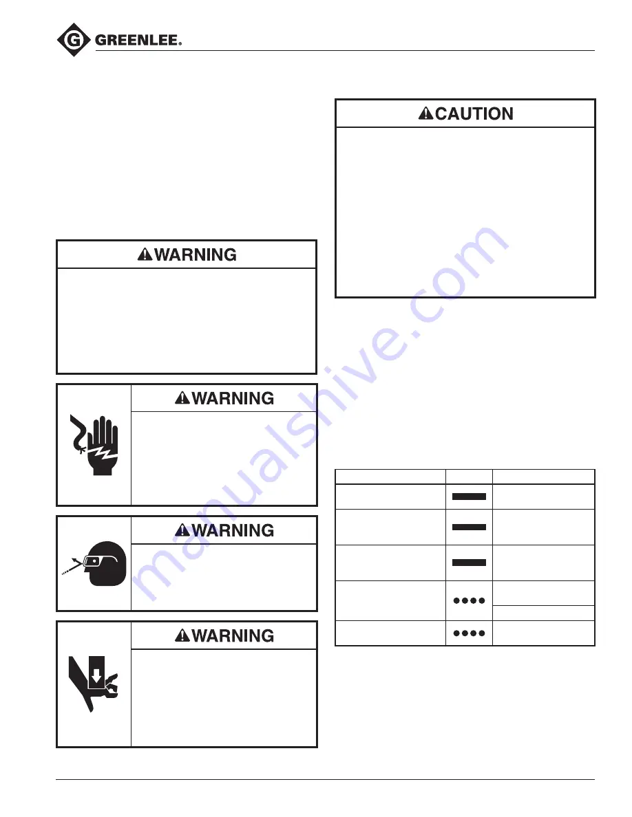
•  Inspect tool and dies before use. Replace any 

worn or  damaged parts. A damaged or improp-

erly  assembled tool can break and strike nearby 

personnel. 

•  Carrying strap is for carrying only, not to be used to 

hang or suspend tool. 

Failure to observe these warnings could result in 

severe injury or death.

Electric shock hazard:
This tool is not insulated. When using 

this unit on or near energized electri-

cal lines, use proper personal protec-

tive equipment.
Failure to observe this warning could 

result in severe injury or death.

Wear eye protection when operating 

or servicing this tool. 
Failure to wear eye protection could 

result in serious eye injury from flying 

debris or hydraulic oil. 

Pinch points:
•  Remove battery before changing 

dies, adapters, or jaws.

•  Keep hands away from the crimp-

ing tool head when crimping.

Failure to observe these warnings 

could result in severe injury or death.

•  Do not use this tool for continuous use. After 30 to 

40 cycles, allow the tool to cool for 15 minutes.

•  Do not secure this tool in a vise. This tool is 

designed for hand-held operation.

•  This tool may be used in damp or wet environ-

ments; however, air-drying is recommended before 

use if the tool becomes soaked. Damage may result 

when the tool is operated prior to thorough drying 

when electrical components are soaked.

•  Use this tool for the manufacturer’s intended 

purpose only.

Failure to observe these precautions may result in 

injury or property damage.

Charging the Battery

Read the instructions supplied with the battery charger.

LED Work Light (white)

This LED automatically turns on when the trigger is 

pulled. It remains on for 10 seconds after the trigger is 

released.

LED Indicator (red)

This tool is equipped with a special circuit board incor-

porating several important features to inform the user 

about the current status of the unit. The LED signals in 

the following cases:

What happens

Signal

What it means

Constant light for 20 seconds 

at end of cycle

Battery charge is below 

17 V at beginning of cycle*

Tool will 

not

 start, and 

constant light for 20 seconds 

when trigger is released

Battery charge is below 

16 V at beginning of cycle*

Tool will stop, and constant 

light for 20 seconds after 

trigger is released

Battery voltage drops 

below 13 V during cycle*

Tool will stop, and flashing 

light for 20 seconds when 

trigger is released


Motor current exceeds 

20 A during cycle
Circuit has become too hot

Flashing light for 20 seconds 

at end of cycle


Send tool in for service

  * Running the battery below 16 V can damage the battery.

Summary of Contents for Greenlee GATOR EK1550FLX

Page 1: ...Inc 10 16 Serial Number Read and understand all of the instructions and safety information in this manual before operating or servicing this tool Register this product at www greenlee com EK1550FLT and EK1550FLX GATOR Battery powered 15 ton Crimping Tools ...

Page 2: ...Greenlee tools and equipment This manual and any markings on the tool provide information for avoiding hazards and unsafe practices related to the use of this tool Observe all of the safety information provided Purpose of this Manual This manual is intended to familiarize all personnel with the safe operation and maintenance procedures for the following Greenlee tools EK1550FLT Battery powered Cri...

Page 3: ...ent Failure to observe this warning could result in severe injury or death Wear eye protection when operating or servicing this tool Failure to wear eye protection could result in serious eye injury from flying debris or hydraulic oil Skin injection hazard Do not use hands to check for oil leaks Oil under pressure easily punc tures skin If injured seek medical attention immediately to remove oil F...

Page 4: ...hen electrical components are soaked Use this tool for the manufacturer s intended purpose only Failure to observe these precautions may result in injury or property damage Do not allow anything to contact the battery terminals Do not immerse the batteries in liquid Liquid may create a short circuit and damage the battery If bat teries are immersed contact your service center for proper handling D...

Page 5: ...r Specifications Crimping Capacities Maximum Crimping Capacity Aluminum 1250 kcmil Copper 1500 kcmil With P Style Dies no adapter kit needed 1250 kcmil aluminum and 1500 kcmil copper fittings With 52060610 Die Adapter Set for 12 ton U Style Dies 500 kcmil copper splices 750 kcmil copper terminals 350 kcmil aluminum splices 750 kcmil aluminum terminals Note Do not use non butting dies crimps contro...

Page 6: ...o connectors and or conductors 3 Slide top die into place in die holder while simultaneously squeezing retainer button Release button and allow die to snap into place Repeat operation for other die entry Adapter Kits Procedure for Using 12 ton U Style Dies with 52060610 Die Adapter Set 1 Slide a die adapter assembly into the flip top head while depressing the die retainer button Release the retain...

Page 7: ...uous use After 30 to 40 cycles allow the tool to cool for 15 minutes Do not secure this tool in a vise This tool is designed for hand held operation This tool may be used in damp or wet environ ments however air drying is recommended before use if the tool becomes soaked Damage may result when the tool is operated prior to thorough drying when electrical components are soaked Use this tool for the...

Page 8: ...mp complete the number of crimps specified under Connector Selection 5 For a single crimp position the connector so the crimp will be located at the center of the barrel Crimping Direction evenly spaced First Compression Crimping Direction SIDE A evenly spaced Crimping Direction SIDE B evenly spaced First Compression SIDE A First Compression SIDE B 6 Depress the trigger to advance the ram Hold the...

Page 9: ...ugs Use the number of crimps listed in this column instead of the number provided with the connector Die Selection Refer to Connector Selection for brand names and model numbers of appropriate lugs as well as crimping instructions Crimps made with this tool and KC12 type or KA12 type dies are cUL and UL classified when used with the appropriate conductor and connectors listed below Dies for Copper...

Page 10: ...ary 13 Real time clock not found 14 Bluetooth unit not found 15 Mobile unit not found 16 Pressure sensor not found 17 Burst pressure exceeded 18 Battery temperature too low If there is no error code cycle through the various displays using the left and right buttons on either side of the screen There are seven displays in total Display Information Shown 1 Bluetooth status battery charge current pr...

Page 11: ...away from the crimp ing tool head when crimping Failure to observe these warnings could result in severe injury or death Relief valve adjustments must be done by an authorized service center Daily Before use 1 Inspect the tool for wear or damage such as cracks gouges or chips 2 Inspect the tool for damage or leaks 3 Inspect the rotation of the head assembly Fully retract the ram The head should ro...

Page 12: ...n simultane ously Run for approximately 10 seconds and then attempt to crimp If unsuccessful contact Greenlee customer service at 800 435 0786 for warranty service or repair Cold oil Pull trigger and hold retract button simultaneously to warm oil Store tool in warm area Tool loses oil Damaged seal Contact Greenlee customer service at 800 435 0786 for warranty service or repair Troubleshooting Befo...

Reviews: