background image

25

DRIFTLESS

SPRAYER

ITEM

PART NO.

DESCRIPTION

QTY

ITEM

PART NO.

DESCRIPTION

QTY

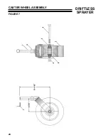
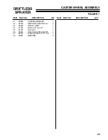
CASTER WHEEL ASSEMBLY

FIGURE 7

7-1

00865

CASTER BRACKET

1

7-2

00159

SPACER-CASTER WHL

2

7-3

00920

WHEEL ASSY

1

7-4

01166

BOLT-5/8" X 6-1/2"

1

7-5

01051

NUT-5/8"

1

7-6

00853

SPACER-CASTER BRKT

1

7-7

05116

LYNCH PIN-3/16" X 1-1/2"

1

7-8

00857

BEARING

2

Summary of Contents for 73-70675

Page 1: ...ntain this machine should be trained in its proper use warned of its dangers and should read the entire manual before attempting to set up operate adjust or service the machine ASSEMBLY OPERATIONS MAN...

Page 2: ...of California to cause cancer birth defects or other reproductive harm California Advertencia de la Proposicion 65 El estado de California hace saber que los gases de escape de los motores diesel y a...

Page 3: ...acobsen replacement parts because they are manufactured with the same high precision and quality as the original parts Jacobsen designs and builds its equipment to serve many years in a safe and produ...

Page 4: ...other persons Assembly Safety Clear large area to fold booms out in field position A minimum of two people should be available for assembly of large equipment especially when lifting or exertion is r...

Page 5: ...ress Number bars 800067 2 07 2 76 4 14 2 07 2 76 4 14 80015 2 07 2 76 4 14 2 07 2 76 4 14 2 07 2 76 4 14 2 07 2 76 4 14 2 07 2 76 4 14 2 07 2 76 4 14 2 07 2 76 4 14 Tip 8001 8002 8003 8004 8005 8006 8...

Page 6: ...tc Always check the flow by the above calibration method Table 2 Time in Seconds to Travel Distance of Table 3 Time in Seconds to Travel a Distance of mph 10 ft 25 ft 50 ft 100 ft 200 ft 1 1 5 2 2 5 3...

Page 7: ...and finally with clean water Check with your chemical agent Whenever pesticides are changed or before sprayer storage clean sprayers thoroughly with a cleaning solution The solution used depends on t...

Page 8: ...ter boom section when the spray boom hits a large object The wings break away to protect the object being contacted and the sprayer itself Center Frame The Center Frame supports the solution tank supp...

Page 9: ...t 48 on drawing 12686 3 On the right boom pull upright tube attach the eyebolt with two pulleys using the nut supplied in the parts bag On the left boom pull upright tube attach the eyebolt with one p...

Page 10: ...ing rope pull tab Run the shortest rope to the right upright tube through the pulley and down to the right wing rope pull tab 13 Tie a tight knot in the very end of the rope Pull rope back out of the...

Page 11: ...ess 2 Grease all grease nipples There are two nipples at each wing pivot one nipple for the Center Castor Frame pivot and one nipple for each castor wheel pivot 3 Operate the front mount sprayer throu...

Page 12: ...bove the spray pressure desired for the specific tip type and chemical The exact difference between the set pressure with no booms spraying and the spray pressure will depend on the size of tips and n...

Page 13: ...11 DRIFTLESS SPRAYER PARTS SECTION PARTS SECTION...

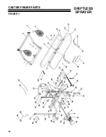
Page 14: ...12 DRIFTLESS SPRAYER CASTER FRAME PARTS FIGURE 1...

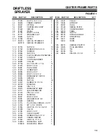
Page 15: ...AWAY CATCH 2 1 27 00955 SPRING 2 1 28 00956 NUT 3 8 30 1 29 12272 SCREW 1 4 X 1 1 4 4 1 30 00130 BUSHING 4 1 31 00804 PIN 1 X 6 3 1 32 00470 BREAKAWAY ARM 2 1 33 12717 LEG STEINER FM 2 1 34 01319 PIN...

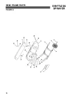
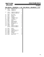
Page 16: ...14 DRIFTLESS SPRAYER WING FRAME PARTS FIGURE 2...

Page 17: ...8 2 2 7 01505 CURTAIN 2 2 8 01504 CURTAIN HANGER 2 2 9 00951 U CLAMP 4 2 10 05447 BOLT 5 16 X 2 2 2 11 06307 ROPE 2 2 12 12057 BACKING WING 2 2 13 01154 BOLT 1 4 X 3 4 6 2 14 01157 WASHER FLAT 1 4 2 2...

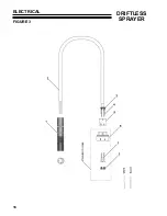
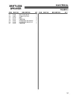
Page 18: ...16 DRIFTLESS SPRAYER ELECTRICAL FIGURE 3...

Page 19: ...RIPTION QTY ITEM PART NO DESCRIPTION QTY ELECTRICAL 3 1 12724 ELEC CON MALE 1 3 2 12813 CABLE 14 2 X 60 1 3 3 01216 SEAL 4 3 4 01215 TERMINAL 2 3 5 01274 CONN WEA PAK 2M 06L 1 3 6 01276 CONN WEA PAK 2...

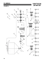
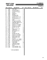
Page 20: ...18 DRIFTLESS SPRAYER PLUMBING FIGURE 4...

Page 21: ...8 12820 HOSE 1 2 X 148 300PSI 1 4 19 12689 HOSE 1 2 X 91 300PSI 1 4 20 12687 HOSE 1 2 X 88 300PSI 1 4 21 11983 ROTOMETER ASSY 2 4 22 12362 NUT 14 4 23 00831 NOZZLE BODY ASSY 4 4 24 00829 SCREEN TIP 14...

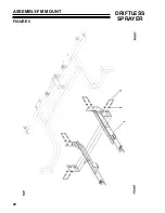
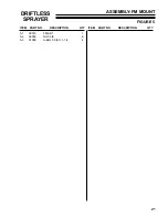
Page 22: ...20 DRIFTLESS SPRAYER ASSEMBLY FM MOUNT FIGURE 5...

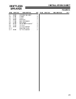
Page 23: ...21 DRIFTLESS SPRAYER ITEM PART NO DESCRIPTION QTY ITEM PART NO DESCRIPTION QTY ASSEMBLY FM MOUNT FIGURE 5 5 1 00013 FM ADT 1 5 2 00956 NUT 3 8 8 5 3 01050 U BOLT 3 8 X 1 1 2 4...

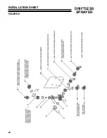
Page 24: ...22 DRIFTLESS SPRAYER INSTALLATION SHEET FIGURE 6...

Page 25: ...NSTALLATION SHEET FIGURE 6 6 1 00889 ROTOMETER BODY 1 6 2 11984 O RING 6 6 3 11976 CLIPS 4 6 4 00909 END CAP 1 6 5 11989 BALL RETAINER 1 6 6 11990 BALL RED 1 6 7 01115 3 4 STREET ELBOW 2 6 8 11975 1 2...

Page 26: ...24 DRIFTLESS SPRAYER CASTER WHEEL ASSEMBLY FIGURE 7...

Page 27: ...DESCRIPTION QTY CASTER WHEEL ASSEMBLY FIGURE 7 7 1 00865 CASTER BRACKET 1 7 2 00159 SPACER CASTER WHL 2 7 3 00920 WHEEL ASSY 1 7 4 01166 BOLT 5 8 X 6 1 2 1 7 5 01051 NUT 5 8 1 7 6 00853 SPACER CASTER...

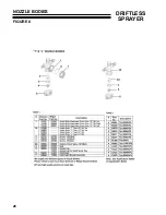
Page 28: ...26 DRIFTLESS SPRAYER NOZZLE BODIES FIGURE 8...

Page 29: ...a Textron company is built to exacting standards ensured by ISO 9001 and ISO 14001 registration at all our manufacturing locations A worldwide dealer network and factory trained technicians backed by...

Reviews: