


Page 2
CL-B101D40-TCRTD Manual (d0099)
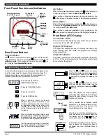
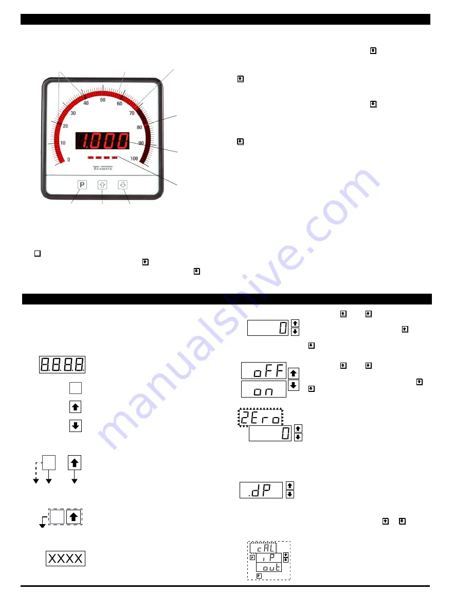
Front Panel Buttons
Program Button
The
P
button is used to move from one program step to the next.
When pressed at the same time as the button, it initiates the
calibration mode. When pressed at the same time as the but-
ton, it initiates the setpoint setting mode.
101 Segment
Bargraph
Up Button
When in the operational display, pressing the button allows you
to view the setting of the saved Peak and Valley Values.
When setting a displayed parameter during programming, the
button is used to increase the value of the displayed parameter.
Down Button
When in the operational display, pressing the button allows you
to change the Brightness Level as well as to view the setting of
the setpoints SP1, SP2, SP3 & SP4.
When setting a displayed parameter during programming, the
button is used to decrease the value of the displayed parameter.
Front Panel LED Display
Annunciator LEDs
The annunciator LEDs indicate the alarm status. They are labeled
from bottom to top: SP1, SP2, SP3, SP4.
Digital LED Displays
The digital LED displays are used to display the meter input
signal readings. They also display the programming settings
during programming.
Setpoint Indication
The position of setpoints on the bargraph display are indicated by
an ON or OFF segment dependent on the bargraph display being
above or below the setpoint.
Setpoints
indicated
by an ON
Segment
Setpoints indicated
by an OFF Segment
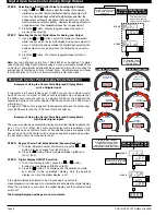
Controls and Indicators
This symbol represents the
OPERATIONAL DISPLAY.
This is the PROGRAM button.
This is the UP button.
This is the DOWN button.
When a button is shown, press and
release it to go onto the next step in the
direction indicated by the arrow. When
an alternative dotted line is shown, this
indicates that an alternative logic branch
will be followed when a particular option
is present.
When two buttons are shown side by side
and enclosed by a dotted line, they must
be pressed at the same time then released
to go onto the next programming step.
If an X appears through a digit, it means that
any number displayed in that digit is not rel-
evant to the function being explained.
P
[Span]
[10000]
P
P
When the and buttons are shown
together, the display value can be increased
by pressing and releasing the button
or decreased by pressing and releasing the
button.
When the and buttons are shown
with two displays, either display can be
selected by pressing and releasing the or
buttons.
When two displays are shown together
with bursts, this indicates that the display is
toggling (flashing) between the name of the
function and the value.
Text or numbers shown between square
brackets in a procedure indicate the pro-
gramming code name of the function or the
value displayed on the meter display.
When there are more than two display selec-
tions they are shown in brackets below the
first display and are also selectable by
pressing and releasing the or buttons.
A dotted line enclosing an entire logic dia-
gram indicates that programming branch
will appear only when a particular option is
present.
To explain software programming procedures, logic diagrams are
used to visually assist in following the programming steps. The
following symbols are used throughout the logic diagrams to
represent the buttons and indicators on the meter:
Programming Conventions
[X•XXX]
[XX•XX]
[XXX•X]
[XXXX•]
[XXXX]
Front Panel Controls and Indicators
LED
Annunciators
for Setpoints
1-4
Single or
Tri-color
Bargraaph
Display
UP
Button
DOWN
Button
PROGRAM
Button
7 Segments
Digital
Display


