64
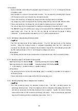
9-7-6. Setting tracking voltage/current
・
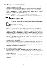
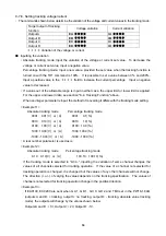
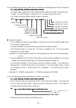
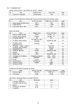
The commands shown below determine the variation of the voltage and current values in the tracking mode.
Target output of tracking
function
Voltage variation
Current variation
Output A
EA
****
IA
****
Output B
EB
****
IB
****
Output C
EC
****
IC
****
Output D
ED
****
ID
****
*
***
: Variation of the voltage or current
■
Inputting the variation
・
Absolute tracking mode: Input the variation of the voltage or current set value. To decrease the
voltage or current set value, input a negative value.
・
Percentage tracking mode: Input a new value, provided the set value when the tracking function is
turned on with the TO1 command is 100%. It is possible to set a value between 0%. and 200%.
Input a positive value in the
****
field to increase the current percentage. Input a negative
value to decrease it.
・
If a value out of the allowable range is input in either case, the upper limit or lower limit is applied.
For the upper and lower limits, see section "6-4. Tracking Function" above.
・
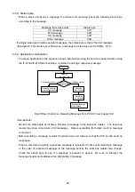
When an integer parameter is input, the method of converting it differs with the tracking mode setting.
< Example 11>
Absolute tracking mode
Percentage tracking mode
0001
:
0.01
[
V
]
or
[
A
]
0001
:
0.1
[%]
0010
:
0.10
[
V
]
or
[
A
]
0010
:
1.0
[%]
0100
:
1.00
[
V
]
or
[
A
]
0100
:
10.0
[%]
1000
:
10.00
[
V
]
or
[
A
]
1000
:
100.0
[%]
-1000
:
-10.00
[
V
]
or
[
A
]
-1000
:
-100.0
[%]
・
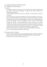
A real number parameter is used as is.
< Example 12>
Absolute tracking mode
Percentage tracking mode
0.10
:
0.10
[
V
]
or
[
A
]
100.10
:
100.10
[%]
・
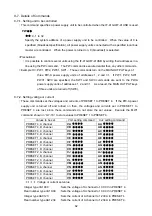
If the tracking mode is selected in “9-7-4.”, inputting the variation of some channel changes the
values of all channels selected for tracking operation. If the value of a channel not selected for
tracking operation is changed, it is changed but the values of any other channels will not change.
The direction (+ or -) of varying the values depends on the tracking specification. The values of
channels not selected for tracking operation change in the positive direction.
< Example 13>
If EA0100, EC0200 are sent when GA 1, GB 1, GC 0, GD 2 and TM0 set in the PW18-1.8AQ
(outputs A and B: + tracking, output C: no tracking, output D: - tracking, absolute value tracking
mode), the outputs will change by the values shown below.
Outputs A and B : +1V, Output C: +2V, Output D: -1V.

