


General Configurations
www.ti.com
10
SLVUA44B – June 2014 – Revised July 2017
Submit Documentation Feedback
Copyright © 2014–2017, Texas Instruments Incorporated
TPS25940EVM-635: Evaluation Module for TPS25940X
4.4.1.4
Current Limit Tests
•
Verify all three current limits (CH1 and CH2,
with only 1 channel powered at a time
) and verify the
latch and auto-retry feature. Setup the oscilloscope as shown in
Table 9
.
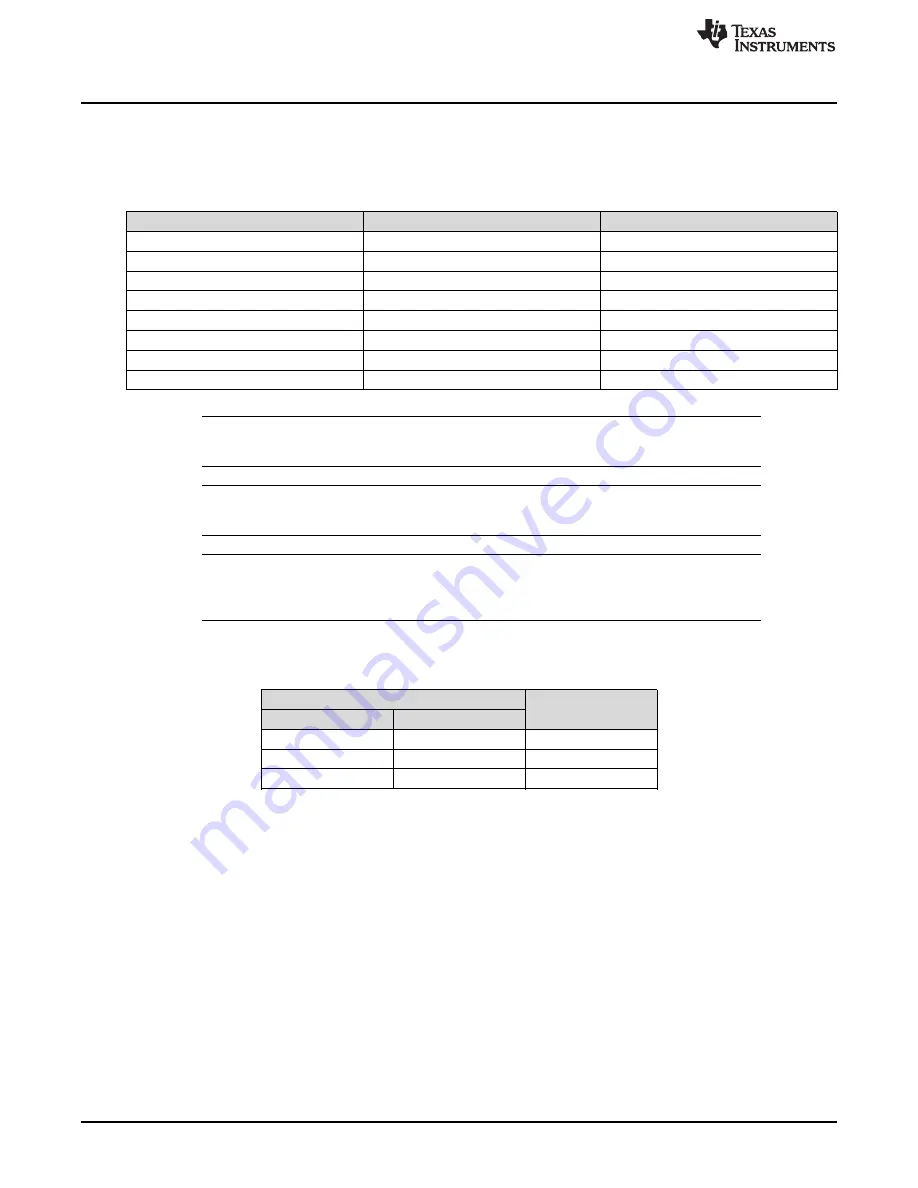
Table 9. PWR635 Oscilloscope Settings for Current Limit Test
Oscilloscope setting
CH1 Probe Points
CH2 Probe Points
Channel 1 = 5 V/div
TP2 = VOUT1
TP16 = VOUT2
Channel 2 = 5 V/div
TP3 = VIN1
TP15 = VIN2
Channel 4 = 2 A/div
Input current into J3 +ve wire
Input current into J8 +ve wire
Trigger source = Channel 4
Trigger level = 1.0 ±0.2 A
Trigger polarity = +ve
Trigger Mode
AUTO
Single Sequence
Time base
40 ms/div
100 ms/div
NOTE:
If an electronic load is used, ensure that the output load is set to constant resistance mode
and not constant current mode.
NOTE:
Measuring Current Limit values on the oscilloscope can easily cause 10% error from
anticipated values listed in
Table 10
.
NOTE:
Since the pulse width of current can vary significantly with the VIN ramp rate, which varies
from one power supply to another, do
not
worry about matching the pulse widths of
Figure 5
and
Figure 6
.
•
The jumper setting for the different current limit test is shown in
Table 10
.
Table 10. PWR635 Jumper Setting for Current Limits
Jumper Position
Load Current Limit
(A)
J4 (CH1)
J9 (CH2)
HI
HI
5.3
LO
LO
3.6
No Jumper
No Jumper
2.1


