background image

www.ti.com

3

Schematic and Bill of Materials

3.1

TPA6040A4 EVM Schematic

S001

Schematic and Bill of Materials

Figure 2. TPA6040A4 EVM Schematic

SLOU196 – April 2007

List of Tables

5

Submit Documentation Feedback

Summary of Contents for TPA6040A4

Page 1: ...les 1 Gain Settings 4 The TPA6040A4 evaluation module consists of a single 2 W stereo speaker amplifier and 85 mW DirectPath headphone amplifier complete with a small number of external components mounted on a circuit board that can be used to drive speakers and headphones directly with external analog audio sources as inputs The TPA6040A4 also contains an LDO capable of outputting 4 75 V with a m...

Page 2: ...r Amplifier EVM Top View Supply voltage range VDD 4 5 V to 5 5 V Supply current IDD 1 A maximum Speaker amplifier output power per channel PO 4Ω VDD 5V THD N 10 2 W Headphone output power per channel PO 32 Ω VDD 5V THD N 10 85 mW List of Tables 2 SLOU196 April 2007 Submit Documentation Feedback ...

Page 3: ...J16 Connect another speaker across ROUT J17 and ROUT J18 3 Install both gain jumpers GAIN0 J5 and GAIN1 J6 This sets the gain of the amplifier to the lowest level 6 dB 4 Connect a set of headphones to the headphone output jack J10 Control Inputs 1 Speaker Enable This terminal is active low A LOW on the device terminal 0 8 V enables the amplifier a HIGH 2 V on the device terminal places the amplifi...

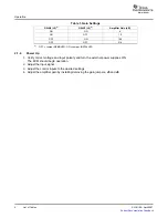
Page 4: ...VED ON Jumper INSTALLED 1 Verify correct voltage and input polarity and turn the external power supplies ON The EVM should begin operation 2 Adjust the input signal 3 Adjust the control inputs to the desired settings 4 Adjust the amplifier gain by installing removing the gain jumpers J5 and J6 List of Tables 4 SLOU196 April 2007 Submit Documentation Feedback ...

Page 5: ... ti com 3 Schematic and Bill of Materials 3 1 TPA6040A4 EVM Schematic S001 Schematic and Bill of Materials Figure 2 TPA6040A4 EVM Schematic SLOU196 April 2007 List of Tables 5 Submit Documentation Feedback ...

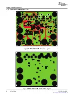
Page 6: ...2 TPA6040A4 EVM PCB Layers K001 K002 Schematic and Bill of Materials Figure 3 TPA6040A4 EVM Top Side Layout Figure 4 TPA6040A4 EVM Bottom Side Layout 6 List of Tables SLOU196 April 2007 Submit Documentation Feedback ...

Page 7: ...3 1 ND 20 R1 R5 Resistor chip 100 kΩ 1 10W 5 0603 5 Panasonic ERJ 3GEYJ104V Digi Key P100KG J1 J2 J11 J12 Phono jack PC mount switched 4 Switchcraft PJRAN1X1U03 Newark 16C1860 J3 J7 Header 2 position male 2 mm 5 Norcomp 2163 36 01 P2 Digi Key 2163S 36 J10 Headphone jack 3 Kycon Inc STX 3081 5N Mouser 806 STX 3081 5t Banana jack w knurled thumbnut nickel J15 J18 6 Johnson 111 2223 001 Digi Key J587...

Page 8: ...ceptive business practice TI is not responsible or liable for any such statements TI products are not authorized for use in safety critical applications such as life support where a failure of the TI product would reasonably be expected to cause severe personal injury or death unless officers of the parties have executed an agreement specifically governing such use Buyers represent that they have ...

Reviews: